Do you have a question about the Sony HCD-M300AV and is the answer not in the manual?
Details of CD, Tape, Tuner, AM tuner sections, and overall system specs.
Amplifier power specifications, inputs, and outputs.
Precautions for optical pick-up, laser diode, and chip components.
Guidelines for flexible circuit boards and chip component replacement.
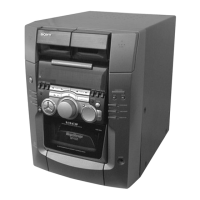
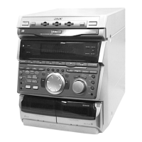
Identification of controls and indicators on the front panel.
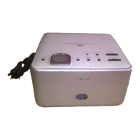
Identification of connectors and ports on the rear panel.
Steps for removing case, front panel, and door assemblies.
Procedures for back panel, main board, and power transformer removal.
Instructions for CD, tape, optical pick-up, panel, and cassette board removal.
Procedures for cold/hot reset, CD initial, and CD memo clear operations.
GC Test, Aging Mode, AM Tuner, CD SRAM, and VACS test procedures.
Procedures and torque measurements for tape deck mechanical adjustments.
Alignment procedures for disc sensor, magnet assembly, and disc holder.
Adjustments for tape deck azimuth, speed, and playback level.
S-curve, E-F balance, RF level, and PLL free-run checks.
High-level diagrams and circuit board component placement.
Detailed circuit schematics for various system sections.
Signal characteristics, IC pin descriptions, and internal IC block diagrams.
Visual breakdown of case, panel, chassis, and mechanism components.
Detailed parts lists for BD, Panel, Amp, and other system boards.
Listings for power transformers, hardware, and other miscellaneous items.
| CD Player | Yes |
|---|---|
| Audio Channels | 2.0 |
| Remote Control | Yes |
| Type | Mini Hi-Fi System |
| Functions | CD Player, Cassette Deck |
| Tuner Bands | AM/FM |
| Cassette Deck | Yes |
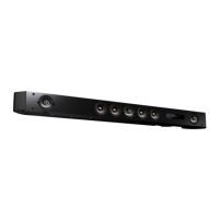
| Speaker Type | 2-way |