Do you have a question about the Sony HCD-RG170 and is the answer not in the manual?
Handling precautions for optical pick-up block to prevent electrostatic breakdown.
Guidelines for safely checking the laser diode emission from the optical pick-up block.
Procedure for checking laser diode and focus search operation using S curve.
Instructions for identifying different types of main boards used in the set.
Information on identifying the model based on the back panel label indication.
List of abbreviations used for model destinations and regional variations.
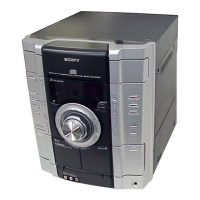
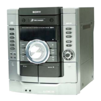
Identifies and locates all controls and buttons on the main unit of the set.
Explains the function of various buttons found on the main unit.
Lists remote control buttons alphabetically for easy reference.
Explains the functions of individual buttons on the remote control.
Provides a step-by-step flow chart for disassembling the set.
Instructions for removing the top case of the unit.
Procedure for disassembling the CD door mechanism.
Steps for removing and disassembling the front panel section.
Details on disassembling the mechanical CD deck mechanism.
Instructions for disassembling the CD mechanism deck, specifying model variations.
Procedure for accessing and removing the back panel section.
Steps for disassembling and removing the main board.
Procedure for disassembling the BD board and CD board.
Instructions for disassembling the driver board and SW board.
Steps for disassembling the optical pick-up block.
Procedure for disassembling the sensor board.
Instructions for disassembling the motor (TB) board.
Steps for disassembling the motor (LD) board.
Clears all preset data to initial conditions; used when returning the set to the customer.
Allows changing the AM tuning interval between 9 kHz and 10 kHz.
Moves optical pick-up to a position durable to vibration for returning the set to the customer.
Performs CD ship mode and cold reset simultaneously.
Mode to prevent sample disc removal from the tray in the shop.
Displays amplifier IC parameters and VACS status, allows adjustment.
Contains adjustments and checks for the CD playback block.
Procedure to confirm symmetrical S-curve waveform and peak-to-peak level.
Procedure to check the RFAC signal waveform and level for clear distinction.
Illustrates the block diagram for the CD servo system.
Shows the block diagram for the audio and video signal processing sections.
Depicts the block diagram for the amplifier section, including power stages.
Illustrates the block diagram for the panel controls and power supply circuits.
Shows the component layout for the CD board (excluding MX model).
Provides the schematic diagram for the CD board (excluding MX model).
Shows the component layout for the BD board (MX model only).
Provides the schematic diagram for the BD board (MX model only).
Shows the component layout for the changer section boards.
Provides the schematic diagram for the changer section.
Shows the component layout for the MAIN board (Suffix-11).
Provides the schematic diagram for the MAIN board (1/3) (Suffix-11).
Provides the schematic diagram for the MAIN board (2/3) (Suffix-11).
Provides the schematic diagram for the MAIN board (3/3) (Suffix-11).
Shows the component layout for the MAIN board (Suffix-12).
Provides the schematic diagram for the MAIN board (1/3) (Suffix-12).
Provides the schematic diagram for the MAIN board (2/3) (Suffix-12).
Provides the schematic diagram for the MAIN board (3/3) (Suffix-12).
Shows the component layout for the POWER board (GX255/RG170).
Provides the schematic diagram for the POWER board (GX255/RG170).
Shows the component layout for the POWER board (RG470: AEP, EE, RU).
Provides the schematic diagram for the POWER board (RG470: AEP, EE, RU).
Shows the component layout for the POWER board (RG470: E2, E51, AR, MX).
Provides the schematic diagram for the POWER board (RG470: E2, E51, AR, MX).
Shows the component layout for the audio in, mic, and headphone boards.
Provides the schematic diagram for the audio in, mic, and headphone boards.
Shows the component layout for the CD-G section (MX model only).
Provides the schematic diagram for the CD-G section (MX model only).
Shows the component layout for the panel section (1/2).
Shows the component layout for the panel section (2/2).
Provides the schematic diagram for the panel section (1/2).
Provides the schematic diagram for the panel section (2/2).
Shows the component layout for the TRANS section (GX255/RG170).
Provides the schematic diagram for the TRANS section (GX255/RG170).
Shows the component layout for the TRANS section (RG470: AEP, EE, RU).
Provides the schematic diagram for the TRANS section (RG470: AEP, EE, RU).
Shows the component layout for the TRANS section (RG470: E2, E51, AR, MX).
Provides the schematic diagram for the TRANS section (RG470: E2, E51, AR, MX).
List of abbreviations used for model destinations and regional variations.
Exploded view of the overall unit, showing major assemblies and parts with reference numbers.
Exploded view detailing parts of the back panel section.
Exploded view of the front panel section, including controls and display elements.
Exploded view detailing the various keys and their mounting on the panel.
Exploded view illustrating the internal chassis structure and component placement.
Exploded view showing the transformer board and related components.
Exploded view of the CD mechanism deck, first part, detailing its components.
Second part of the exploded view for the CD mechanism deck, showing detailed components.
| Power Output | 100 W |
|---|---|
| CD Player | Yes |
| Radio Tuner | Yes |
| Tuner Bands | AM/FM |
| Bluetooth | No |
| USB Playback | No |
| USB Port | No |
| Cassette Deck | Yes |
| Speakers | 2 |
| Remote Control | Yes |
| Type | Mini Hi-Fi System |
| RMS Output Power | 50W |