EasyManua.ls Logo

Sony HCD-RG11 User Manual

Sony HCD-RG11
50 pages
To Next Page IconTo Next Page
Page #1 background imageLoading...
Page #1 background image
HCD-RG11
AEP Model
UK Model
SERVICE MANUAL
MINI HIFI COMPONENT SYSTEM
SPECIFICATIONS
Ver 1.2 2004. 08
HCD-RG11 is the tuner, deck, CD and
amplifier section in MHC-RG11.
Model Name Using Similar Mechanism HCD-RG20
CD
CD Mechanism Type CDM58F-K6
Section
Optical Pick-up Name
KSM-213D
Tape deck Model Name Using Similar Mechanism HCD-RG20
Section Tape Transport Mechanism Type CWL44FF29
Sony Corporation
Audio Group
Published by Sony Engineering Corporation
9-874-039-03
2004H16-1
© 2004.08
Amplifier section
DIN power output (rated) 40 + 40 watts
(6 ohms at 1 kHz, DIN)
Continuous RMS power output (reference)
50 + 50 watts (6 ohms at 1
kHz, 10% THD)
Music power output (reference)
95 + 95 watts (6 ohms
at 1 kHz, 10% THD)
Inputs
GAME (AUDIO) IN (phono jack):
voltage 450 mV,
impedance 47 kilohms
Outputs
PHONES (stereo mini jack):
accepts headphones of
8 ohms or more
Front speaker: accepts impedance of 6 to
16 ohms
CD player section
System Compact disc and digital
audio system
Laser Semiconductor laser
(λ=780 nm)
Emission duration:
continuous
Frequency response 2 Hz – 20 kHz (±0.5 dB)
Wavelength 780 – 790 nm
Signal-to-noise ratio More than 90 dB
Dynamic range More than 90 dB
Tape deck section
Recording system 4-track 2-channel stereo
Frequency response 40 – 13,000 Hz (±3 dB),
using Sony TYPE I
cassette
Tuner section
FM stereo, FM/AM superheterodyne tuner
FM tuner section
Tuning range 87.5 – 108.0 MHz
Antenna FM lead antenna
Antenna terminals 75 ohm unbalanced
Intermediate frequency 10.7 MHz
AM tuner section
Tuning range 531 – 1,602 kHz (with the
interval set at 9 kHz)
Antenna AM loop antenna
Antenna terminals External antenna terminal
Intermediate frequency 450 kHz
General
Power requirements 230 V AC, 50/60 Hz
Power consumption 85 watts
1.0 watts (at the Power
Saving Mode)
Dimensions (w/h/d)
Approx. 280 × 325 × 421 mm
Mass Approx. 8.1 kg
Design and specifications are subject to change
without notice.
w
w
w
.
x
i
a
o
y
u
1
6
3
.
c
o
m
Q
Q
3
7
6
3
1
5
1
5
0
9
9
2
8
9
4
2
9
8
T
E
L
1
3
9
4
2
2
9
6
5
1
3
9
9
2
8
9
4
2
9
8
0
5
1
5
1
3
6
7
3
Q
Q
TEL 13942296513 QQ 376315150 892498299
http://www.xiaoyu163.com
Question and Answer IconNeed help?

Do you have a question about the Sony HCD-RG11 and is the answer not in the manual?

Sony HCD-RG11 Specifications

General IconGeneral
Power Output100 W
CD PlayerYes
TunerAM/FM
Cassette DeckYes
MP3 PlaybackYes
Remote ControlYes
Speakers2 Speakers
FunctionsCD, Cassette
TypeMini Hi-Fi Component System

Summary

Product Specifications and Overview

Amplifier, CD, and Tape Deck Specifications

Detailed specifications for the amplifier, CD player, and tape deck sections.

Tuner and General Specifications

Specifications for the tuner section, power requirements, dimensions, and mass.

Critical Handling and Safety Precautions

Optical Pick-up and Laser Diode Handling

Notes on handling the optical pick-up block and laser diode emission checks.

Component Replacement and Repair Safety

Guidelines for chip component replacement and flexible circuit board repair.

Safety-Related Component Warning

Warning about critical safety components identified by mark.

Main Unit Controls and Identification

Main Unit Component Diagram

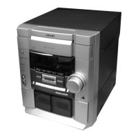
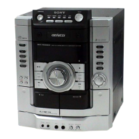
Labeled diagram identifying main unit components and their locations.

Main Unit Button Functions

Descriptions of the functions for each button on the main unit.

Remote Control Operations

Remote Control Layout and Button Functions

Labeled diagram of the remote control and descriptions of its buttons.

Setting the System Time

Step-by-step procedure for setting the system's clock and time.

Disassembly Procedures Overview

Disassembly Flow and Top Case Removal

Overview of the disassembly sequence and steps for removing the top case.

Front Panel and CD Mechanism Disassembly

CD Door Removal Procedure

Instructions for removing the CD door mechanism.

Front Panel and CD Mechanism Deck Disassembly

Steps for disassembling the front panel and CD mechanism deck.

Internal Component Disassembly

Tape Mechanism and Board Removal

Procedures for disassembling the tape mechanism deck, panel board, and related boards.

Main Unit Internal Disassembly

Main, Power Board, and Base Unit Removal

Steps for removing the main board, power board, and base unit.

CD Section Component Disassembly

CD Board and Associated Components Removal

Procedures for disassembling the CD board, driver board, motor board, and sensor board.

Service Test Modes and Error Codes

Cold Reset and Aging Mode Procedures

Steps for performing a cold reset and operating in aging mode.

Aging Mode Error Displays

Displays indicating errors during aging mode operations for CD and tape.

Special Diagnostic and Operational Modes

Test Mode Descriptions

Explanations of FL Tube, VACS, Version Display, Key Check, CD Service, Equalizer, and CD Ship modes.

Electrical Adjustment Procedures

Tuner Section Adjustments

Procedures for FM tuned level, null adjustment, and AM IF adjustment.

CD Section Performance Checks

CD Section Notes and RF Level Check

Notes for CD section adjustments and procedure for checking RF signal level.

Diagram Conventions and Board Layout

Schematic and PWB Diagram Notes

Notes on schematic and printed wiring board diagram conventions.

Circuit Board Location Diagram

Diagram showing the physical layout of all major circuit boards.

System Block Diagrams

Tuner and CD Section Block Diagram

Block diagram illustrating the interconnections within the tuner and CD sections.

Main System Block Diagram

Main Section Interconnection Diagram

Block diagram showing the overall system's signal flow and connections.

Printed Wiring Board Layouts

CD Section Printed Wiring Board

Layout diagram for the CD section's printed wiring board.

Semiconductor Component Locations

Table mapping semiconductor components to their locations on the CD board.

Schematic Diagrams - CD Section

CD Section Schematic and Waveforms

Schematic diagram for the CD section, including waveform examples.

Main Board Printed Wiring Board Layout

MAIN Board Printed Wiring Board

Layout diagram for the main board's printed wiring board.

Semiconductor Locations on Main Board

Table mapping semiconductor components to their locations on the main board.

Main Board Schematic Diagrams (Part 1)

MAIN Board Schematic (1/4)

The first section of the main board schematic diagram.

Main Board Waveform Examples

Examples of waveforms observed in the main board circuits.

Main Board Schematic Diagrams (Part 2)

MAIN Board Schematic (2/4)

The second section of the main board schematic diagram.

Main Board Waveform Examples

Additional waveform examples from the main board circuits.

Main Board Schematic Diagrams (Part 3)

MAIN Board Schematic (3/4)

The third section of the main board schematic diagram.

Main Board Schematic Diagrams (Part 4)

MAIN Board Schematic (4/4)

The fourth and final section of the main board schematic diagram.

Circuit Board Layouts

Motor, Address Sensor, and Driver Board PWBs

Printed wiring board layouts for the motor, address sensor, and driver boards.

Panel and Video Out Board Details

Panel Section Printed Wiring Board

Layout diagram for the panel section's printed wiring board.

Semiconductor Locations on Panel Board

Table mapping semiconductor components to their locations on the panel board.

Video Out Board Diagram

Diagram illustrating the video out board components.

Panel Section Schematic Diagrams

Panel Section Schematic and Waveforms

Schematic diagram for the panel section with waveform examples.

Power Board Printed Wiring Board Layout

POWER Board Printed Wiring Board

Layout diagram for the power board's printed wiring board.

Semiconductor Locations on Power Board

Table mapping semiconductor components to their locations on the power board.

Trans and Sub-Trans Board Details

Trans Section Printed Wiring Board

Layout diagram for the trans section's printed wiring board.

Sub Trans Board Printed Wiring Board

Layout diagram for the sub trans board's printed wiring board.

Semiconductor Locations for Trans and Sub-Trans Boards

Tables mapping components to locations on trans and sub-trans boards.

Trans Section Schematic Diagrams

Power, Trans, and Sub-Trans Board Schematics

Schematic diagrams for the power, trans, and sub-trans boards.

Integrated Circuit (IC) Block Diagrams

IC Block Diagrams (Part 1)

Block diagrams for various ICs including CD, Tuner, and Sound Processor sections.

Integrated Circuit (IC) Block Diagrams (Continued)

IC Block Diagrams (Part 2)

Block diagrams for additional ICs including Tuner, Driver, and Panel sections.

IC Pin Function Descriptions

IC601 Pin Function Details

Description of pin functions for the IC601 (Master Control) on the Panel Board.

IC Pin Function Descriptions (Continued)

Other IC Pin Function Details

Description of pin functions for other ICs like IC102, LC72131, BD3871, etc.

Exploded Views - Main Section

Main Section Exploded View Diagram

Exploded view illustrating the assembly of the main unit section.

Main Section Parts List

List of part numbers and descriptions for the main section assembly.

Exploded View - Front Panel Section

Front Panel Section Exploded View Diagram

Exploded view illustrating the assembly of the front panel section.

Front Panel Section Parts List

List of part numbers and descriptions for the front panel section assembly.

Exploded View - Main Board Section

Main Board Section Exploded View Diagram

Exploded view illustrating the assembly of the main board section.

Main Board Section Parts List

List of part numbers and descriptions for the main board section assembly.

Exploded View - CD Mechanism Deck Section

CD Mechanism Deck Exploded View Diagram

Exploded view illustrating the assembly of the CD mechanism deck.

CD Mechanism Deck Parts List

List of part numbers and descriptions for the CD mechanism deck assembly.

Electrical Parts List - Address Sensor CD

Address Sensor Board Components

List of electrical components for the address sensor board.

Electrical Parts List - Component Types

Capacitors, Connectors, Diodes, ICs, Coils, Transistors, Resistors

List of various component types including capacitors, connectors, diodes, ICs, coils, transistors, and resistors.

Electrical Parts List - CD, Driver, Main Board Components

CD, Driver, Main Board Capacitors and Connectors

List of capacitors and connectors for CD, Driver, and Main boards.

CD, Driver, Main Board Diodes, ICs, and Resistors

List of diodes, ICs, and resistors for CD, Driver, and Main boards.

Electrical Parts List - Main Board Capacitors and Filters

Main Board Capacitors and Filters

List of capacitors and filters used on the main board.

Main Board Connectors

List of connectors used on the main board.

Electrical Parts List - Main Board Components (Part 1)

Main Board Crystals, Diodes, Coils, Transistors, ICs, IFT, Terminal Board

List of crystals, diodes, coils, transistors, ICs, IFTs, and terminal boards for the main board.

Main Board Resistors (Part 1)

List of resistors for the main board.

Electrical Parts List - Main Board Resistors (Part 2)

Main Board Resistors (Part 2)

Continuation of the resistor list for the main board.

Electrical Parts List - Panel and Motor Components

Panel and Motor Board Resistors, Transformers, and Capacitors

List of resistors, transformers, and capacitors for panel and motor boards.

Panel and Motor Board Connectors, Switches, and Other Components

List of connectors, switches, vibrator, and encoder for panel and motor boards.

Electrical Parts List - Panel Board Components

Panel Board Capacitors, Connectors, Diodes, Ferrite Bead, Indicator, ICs, Jacks

List of capacitors, connectors, diodes, ferrite bead, indicator, ICs, and jacks for the panel board.

Panel Board Resistors, LEDs, Transistors

List of resistors, LEDs, and transistors for the panel board.

Electrical Parts List - Power and Control Components

Power and Panel Board Resistors, Switches, Variable Resistor, Rotary Encoder, Vibrator

List of resistors, switches, variable resistor, rotary encoder, and vibrator.

Power and Panel Board Capacitors

List of capacitors for the power and panel boards.

Electrical Parts List - Power Supply and Interface Boards

Power Board Capacitors, Connectors, Diodes, ICs, Transistors, Resistors

List of components for the power board, including capacitors, connectors, diodes, ICs, transistors, and resistors.

SPDL, Sub Trans Board Components

List of components for the SPDL and Sub Trans boards, including transistors, resistors, relay, and transformer.

Electrical Parts List - Video Output and Related Boards

Trans Board Components and Miscellaneous Items

List of components for the Trans board and miscellaneous items.

Video Out Board Components

List of components for the video out board, including capacitors, connectors, diodes, fuses, fuse holders, transistors, and resistors.

Revision History

Document Revision Records

Records of changes made to the service manual across different versions.

Related product manuals