EasyManua.ls Logo

Sony HCD-RG550 User Manual

Sony HCD-RG550
76 pages
To Next Page IconTo Next Page
Page #1 background imageLoading...
Page #1 background image
1
Ver 1.0 2003. 06
Model Name Using Similar Mechanism NEW
CD CD Mechanism Type CDM74F-K6BD71B
Section Base Unit Name BU-K6BD71B
Optical Pick-up Name KSS-213DCP
Tape Deck Model Name Using Similar Machanism CX-JT8
Section Tape Transport Mechanism Type CWM43RR-23
SERVICE MANUAL
AEP Model
UK Model
E Model
HCD-RG550/RG660
Amplifier section
European model:
HCD-RG660:
Front speaker
DIN power output (rated):
160 + 160 watts
(6 ohms at 1 kHz, DIN)
Continuous RMS power output (reference):
200 + 200 watts (6 ohms at
1 kHz, 10% THD)
Music power output (reference):
400 + 400 watts (6 ohms at
1 kHz, 10% THD)
Other models:
HCD-RG660:
The following measured at AC 120, 127, 220, 240 V,
50/60 Hz
DIN power output (rated):
160 + 160 watts
(6 ohms at 1 kHz, DIN)
Continuous RMS power output (reference):
200 + 200 watts (6 ohms at
1 kHz, 10% THD)
HCD-RG550:
The following measured at AC 120, 127, 220, 240 V,
50/60 Hz
DIN power output (rated):
115 + 115 watts
(6 ohms at 1 kHz, DIN)
Continuous RMS power output (reference):
140 + 140 watts (6 ohms at
1 kHz, 10% THD)
SPECIFICATIONS
Inputs
MD (VIDEO) IN L/R (phono jacks):
voltage 450/250 mV,
impedance 47 kilohms
GAME INPUT AUDIO L/R (phono jacks):
voltage 250 mV,
impedance 47 kilohms
GAME INPUT VIDEO (phono jack):
1 Vp-p, 75 ohms
MIC (phone jack) (except for European model):
sensitivity 1 mV,
impedance 10 kilohms
Outputs
PHONES (stereo mini jack):
accepts headphones of
8 ohms or more
VIDEO OUT (phono jack):
max. output level
1 Vp-p, unbalanced, Sync
negative, load impedance
75 ohms
SPEAKER: accepts impedance of 6 to
16 ohms
SURROUND SPEAKER (HCD-RG660 only):
accepts impedance of 24
ohms
Sony Corporation
Home Audio Company
Published by Sony Engineering Corporation
9-961-000-01
2003F04-1
© 2003. 06
– Continued on next page –
COMPACT DISC DECK RECEIVER
HCD-RG550/RG660 is the
tuner, deck, CD and amplifier
section in MHC-RG550/RG660.
(Photo: HCD-RG550)

Table of Contents

Question and Answer IconNeed help?

Do you have a question about the Sony HCD-RG550 and is the answer not in the manual?

Sony HCD-RG550 Specifications

General IconGeneral
BrandSony
ModelHCD-RG550
CategoryStereo System
LanguageEnglish

Summary

Product Specifications

Amplifier and Speaker Performance

Details rated power output, impedance, and physical dimensions for amplifier and speaker sections.

System Functional Specifications

Covers CD player, tape deck, tuner, general power, and dimensional specifications for the unit.

Safety, Handling, and Model Information

Cautions for Repair and Operation

Provides warnings for component handling, laser safety, and operational precautions.

Model Identification and Test Procedures

Covers model identification, laser checks, and disc tray lock function for service and safety.

Disassembly Procedures

Case and Front Panel Disassembly

Guides the removal of the outer case, CD door, and front panel sections for access.

Internal Mechanism and Board Removal

Details the process for removing the CD mechanism, tape deck, and various internal boards.

Specific Component Access

Covers the disassembly steps for specific components like optical pick-ups and various boards.

Test Modes and Operations

System Initialization and Tuning Test

Explains Cold Reset, Tuner Step Change, and CD Ship Mode procedures.

Special Function Modes

Details modes for MD/Video function changeover, CD Tray Lock, and Amplifier test modes.

Electrical Adjustments, Diagrams, and Waveforms

CD Section Adjustments and Checks

Details CD section adjustments, S-curve checks, and RF level checks for proper operation.

Circuit Diagrams and IC Pinout Information

Provides block diagrams, schematics, and detailed IC pin descriptions for unit sections.

Waveform Analysis and Notes

Illustrates typical waveforms and provides notes on printed wiring board and schematic conventions.

Exploded Views and Parts Lists

Component Breakdown Views

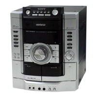
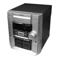
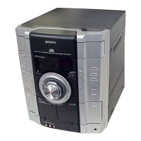
Presents exploded views of main unit, front panel, CD mechanism, and base unit assemblies for parts identification.

Comprehensive Electrical Parts Listing

Lists all electrical components, including resistors, capacitors, diodes, ICs, and transformers, categorized by board.

Revision History

Manual Version 1.0 Details

Records the initial release version, date, and description of the service manual.

Related product manuals