Do you have a question about the Sony HCD-RG30 and is the answer not in the manual?
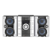
Details amplifier power output and speaker impedance requirements.
Lists CD player system, laser, frequency response, and signal-to-noise ratio.
Covers tape deck, tuner ranges, general specs, power, dimensions, and accessories.
Advises on optical pick-up handling, laser safety, and component replacement precautions.
Lists models and corresponding part numbers, including regional abbreviations.
Procedures for removing/installing panel/key boards and chassis exchange.
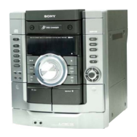
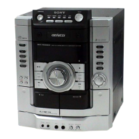
Identifies main unit components and describes button functions.
Details remote button functions and the procedure for setting the system clock.
Steps for disassembling the unit's case, CD door, and front panel.
Instructions for removing tape deck, panel board, key board, and rear components.
Guides for disassembling main, power amp, base unit, BD, driver, motor, and CD mechanism boards.
Covers MC Cold/Hot Reset, CD Ship/Service Modes, AM Tuner Step, GC Test.
Details MC Test Mode and Microprocessor Version Display procedures.
Procedures for Aging Mode, including error display interpretation.
Covers FM adjustments, CD S-Curve, and RF Level checks.
Details E-F Balance and RF PLL Free-run Frequency checks.
Shows board locations and block diagrams for tuner, optical pick-up, and BD section.
Provides block diagrams for optical pick-up/main sections and the BD schematic.
First part of the main board schematic diagram.
Component layout and schematic for the BD board.
Component layout for the main board.
First part of the main board schematic.
Second part of the main board schematic.
Third part of the main board schematic.
Fourth part of the main board schematic.
Fifth part of the main board schematic.
Component layout for the power amplifier board.
Schematic of the power amplifier section.
Component layout for the panel section.
Schematic of the panel section.
Component layout for the transformer section.
Schematic of the transformer section.
Component layout and schematic for the driver section.
Detailed pin functions for the master control IC (IC401) on the main board.
Detailed pin functions for the display control IC (IC701) on the panel board.
Block diagrams for BD board ICs (CXD2587Q, BA5974FP-E2).
Block diagrams for BD and Main board ICs (CXA2568M-T6, BU1924, LC72130).
Block diagrams for Main and Driver board ICs (BA1450, TA8189N, BA6956AN).
Exploded view of the main section, showing major assemblies and parts.
Exploded view of the front panel components and assembly.
Exploded view detailing the chassis, transformer, and wiring harness.
Exploded view of the CD mechanism deck, including motors and gears.
List of components and part numbers for the address sensor board.
List of components and part numbers for the BD driver and key sections.
List of components and part numbers for the panel and key boards.
Comprehensive list of capacitors used on the main board.
List of diodes, filters, and connectors for the main board.
List of transistors and resistors for the main board.
Continued list of transistors and resistors for the main board.
Extensive list of resistors used on the main board.
Final list of resistors, variable resistors, relays, and transformers for the main board.
List of capacitors, connectors, diodes for motor and panel boards.
List of resistors, variable resistors, and capacitors for the panel board.
List of components for power amp and sub-trans boards, including diodes and connectors.
List of components for sub-trans, trans, and video out boards, including fuses and hardware.
Records changes made to the manual across different versions and dates.
| Type | Mini Hi-Fi System |
|---|---|
| CD Player | Yes |
| Tuner | AM/FM |
| Cassette Deck | Yes |
| Audio Channels | 2.0 |
| Remote Control | Yes |