EasyManua.ls Logo

Sony HCD-RG33 User Manual

Sony HCD-RG33
56 pages
To Next Page IconTo Next Page
Page #1 background imageLoading...
Page #1 background image
HCD-GX30/RG22/RG33
Canadian Model
HCD-GX30
AEP Model
UK Model
E Model
HCD-RG22/RG33
Australian Model
HCD-RG22
SERVICE MANUAL
MINI HI-FI COMPONENT SYSTEM
Sony Corporation
Home Audio Company
Published by Sony Engineering Corporation
9-874-001-04
2003L16-1
© 2003.12
HCD-GX30/RG22/RG33 are the tuner,
deck, CD and amplifier section in MHC-
GX30/RG22/RG33.
SPECIFICATIONS
Ver 1.3 2003.12
Model Name Using Similar Mechanism HCD-DX10
CD
CD Mechanism Type CDM58F-K6
Section
Optical Pick-up Name KSM-213D
Tape deck Model Name Using Similar Mechanism NEW
Section Tape Transport Mechanism Type CWL43FF48
Amplifier section
North American models:
HCD-GX30
Continuous RMS power output (reference)
75 + 75 watts (6 ohms at
1 kHz, 10% THD)
Total harmonic distortion less than 0.07%
(6 ohms at 1 kHz, 40 W)
CD player section
System Compact disc and digital
audio system
Laser Semiconductor laser
(λ=780 nm)
Emission duration:
continuous
Frequency response 2 Hz – 20 kHz (±0.5 dB)
Wavelength 780 – 790 nm
Signal-to-noise ratio More than 90 dB
Dynamic range More than 90 dB
Tape deck section
Recording system 4-track 2-channel stereo
Frequency response 50 – 13,000 Hz (±3 dB),
using Sony TYPE I
cassette
Tuner section
FM stereo, FM/AM superheterodyne tuner
FM tuner section
Tuning range 87.5 – 108.0 MHz
Antenna FM lead antenna
Antenna terminals 75 ohms unbalanced
Intermediate frequency 10.7 MHz
European models:
HCD-RG33
DIN power output (rated) 60 + 60 watts
(6 ohms at 1 kHz, DIN)
Continuous RMS power output (reference)
75 + 75 watts (6 ohms at
1 kHz, 10% THD)
Music power output (reference)
150 + 150 watts (6 ohms
at 1 kHz, 10% THD)
HCD-RG22
DIN power output (rated) 50 + 50 watts
(6 ohms at 1 kHz, DIN)
Continuous RMS power output (reference)
60 + 60 watts (6 ohms at
1 kHz, 10% THD)
Music power output (reference)
120 + 120 watts (6 ohms
at 1 kHz, 10% THD)
Other models:
HCD-RG33
The following measured at AC 120, 220, 240 V,
50/60 Hz
DIN power output (rated) 60 + 60 watts
(6 ohms at 1 kHz, DIN)
Continuous RMS power output (reference)
75 + 75 watts (6 ohms at
1 kHz, 10% THD)
HCD-RG22
The following measured at AC 120, 220, 240 V
50/60 Hz
DIN power output (rated) 50 + 50 watts
(6 ohms at 1 kHz, DIN)
Continuous RMS power output (reference)
60 + 60 watts (6 ohms at
1 kHz, 10% THD)
Inputs
AUDIO INPUT (phono jack):
voltage 450 mV,
impedance 47 kilohms
Outputs
PHONES (stereo mini jack):
accepts headphones of
8 ohms or more
Front speaker: accepts impedance of 6 to
16 ohms
Sub woofer speaker (MHC-GX40 only):
accepts impedance of 12
to 16 ohms
— Continued on next page —
Question and Answer IconNeed help?

Do you have a question about the Sony HCD-RG33 and is the answer not in the manual?

Sony HCD-RG33 Specifications

General IconGeneral
CD PlayerYes
Cassette DeckYes
USB PlaybackNo
BluetoothNo
Remote ControlYes
TunerAM/FM
Speakers2
TypeMini Hi-Fi System

Summary

Specifications

Amplifier and Tuner Specifications

Details amplifier power output and tuner frequency specifications across different models.

CD and Tape Deck Specifications

Lists CD player and tape deck performance, including frequency response and laser type.

Safety Check-out Procedures

AC Leakage Measurement

Outlines the method and limits for checking AC leakage from exposed metal parts to ensure safety.

General Unit Overview

Main Unit Components

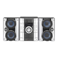
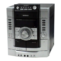
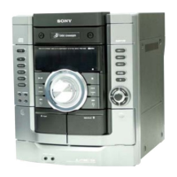
Identifies the main unit and lists front panel controls alphabetically with button descriptions.

Disassembly Instructions

Case, Panel, and Mechanism Disassembly

Covers removal of the unit's exterior case, front panel, and internal mechanisms like CD and tape decks.

Internal Board Removal Procedures

Details the process for accessing and removing internal circuit boards such as the main, power, and sensor boards.

Test Mode Operations

AM Tuner Step Selection

Procedure to switch AM tuner steps between 9 kHz and 10 kHz.

Cold Reset Function

Method to clear all preset data and return the unit to initial conditions.

Aging Mode Operation

Instructions for checking CD and tape deck operation using the aging mode.

Electrical Adjustments

Tuner Section Adjustments

Step-by-step guides for performing AM IF, FM Tuned Level, and Null adjustments on the tuner.

Diagrams and Schematics

Circuit Board Layouts

Diagrams showing the physical placement of all circuit boards within the unit.

Block Diagrams

Explains the functional blocks and signal paths for the CD and Main sections of the unit.

Printed Wiring Boards

Detailed layout diagrams for the CD, MAIN, MOTOR, DRIVER, and ADDRESS SENSOR boards.

Schematic Diagrams

Circuit schematic diagrams for the CD, MAIN, PANEL, POWER, and TRANS sections.

IC Pin Function Descriptions

Lists pin functions for key integrated circuits, detailing their I/O and purpose.

Exploded Views

Main Unit Assembly Views

Illustrates the assembly of the main unit, including the chassis, sub trans board, and fan.

Front Panel Assembly

Exploded view showing the disassembly and reassembly of the front panel, buttons, and associated parts.

CD Mechanism Assembly

Detailed exploded view of the CD mechanism deck, showing all parts and their reference numbers.

Electrical Parts List

CD Section Components

Comprehensive list of electronic parts for the CD section, including capacitors, resistors, diodes, and ICs.

Main Section Components

Detailed list of components for the MAIN section, covering resistors, capacitors, diodes, transistors, and ICs.

Panel Section Components

Parts list for the PANEL section, detailing components like diodes, resistors, switches, and connectors.

Revision History

Manual Update Log

Records the history of updates to the service manual, including version numbers, dates, and revision descriptions.

Related product manuals