Do you have a question about the Sony HCD-RG20 and is the answer not in the manual?
Power output and total harmonic distortion for USA models.
Technical specifications for amplifier, CD player, and tape deck sections.
AC leakage limits and measurement methods for safety.
Critical components warning for safe operation.
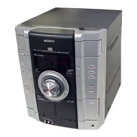
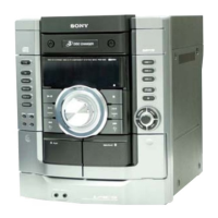
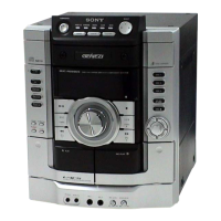
Explains the function of various buttons on the main unit.
Details the functions and operation of the remote control unit.
Step-by-step guide to setting the system's clock time.
Details the steps and parts for disassembling the top case.
Procedure for removing the CD door mechanism.
Steps for disassembling the front panel and CD mechanism.
Instructions for disassembling the tape deck and panel board.
Steps for disassembling the sub trans, video out, and trans boards.
Procedure for removing the main and power boards.
Details the disassembly of the CD base unit components.
Steps for disassembling CD, driver, motor, and address sensor boards.
Procedure to switch AM tuner steps between 9 kHz and 10 kHz.
How to perform a cold reset to clear all data.
Mode for checking CD and tape deck operation.
Tests all fluorescent segments and LEDs.
Mode to switch the VACS (Variable Attenuation Control System) ON/OFF.
Displays the system's version and destination information.
Checks the functionality of each button on the unit.
Allows free movement of the CD sled motor for cleaning.
Tests the functionality of the equalizer settings.
Moves pickup for vibration durability, used before returning to customer.
Adjusts the FM tuned level for optimal reception.
Performs a null adjustment for the tuner section.
Adjusts the AM Intermediate Frequency for proper operation.
Checks the RF signal level output from the CD board.
Shows the physical location of all circuit boards within the unit.
Displays typical waveforms measured at various points on the boards.
Illustrates the overall system block diagram for the Tuner/CD section.
Shows the block diagram for the main audio processing and control sections.
Shows the printed wiring board layout for the CD section.
Provides the schematic diagram for the CD section circuitry.
Shows the printed wiring board layout for the main control and audio sections.
Part 1 of the schematic diagram for the main section.
Part 2 of the schematic diagram for the main section.
Part 3 of the schematic diagram for the main section.
Part 4 of the schematic diagram for the main section.
Shows the printed wiring board layout for address sensor, driver, and motor sections.
Shows the printed wiring board layout for the front panel section.
Provides the schematic diagram for the panel section.
Shows the printed wiring board layout for the power supply section.
Shows the printed wiring board layout for the transformer and sub-trans sections.
Provides the schematic diagram for transformer and sub-trans sections.
Illustrates the block diagrams for key ICs in the CD section.
Details the pin functions for IC601 (Master Control).
Exploded view of the main internal components and their part numbers.
Exploded view of the front panel components and their part numbers.
Exploded view of the main board mounting and associated parts.
Exploded view of the CD mechanism deck assembly and parts.
List of electrical parts for the address sensor and CD sections.
| Brand | Sony |
|---|---|
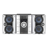
| Model | HCD-RG20 |
| Category | Stereo System |
| Language | English |