Do you have a question about the Sony HCD-RG295 and is the answer not in the manual?
Details power output specifications for front speakers and subwoofer across different models.
Lists available audio input jacks and output connectors for headphones and speakers.
Precautions for handling optical components and checking laser diode emission safely.
Information on unleaded solder usage and flexible circuit board repair temperature.
Procedures to release antitheft lock and warnings on hazardous radiation exposure.
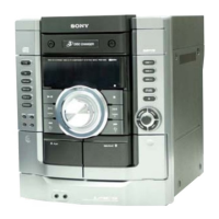
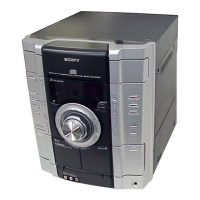
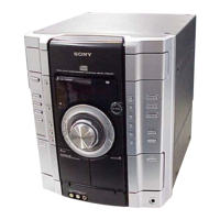
Identifies and explains the function of unit and remote control buttons, indicators, and ports.
Instructions for adjusting sound, playing CDs/MP3s, tapes, and listening to the radio.
Procedures for tuning radio stations and connecting external audio devices.
Guide to programming custom CD track sequences and creating personalized sound effect settings.
Instructions for setting Sleep, Play, and Rec timers for automated system operation.
A visual guide showing the sequence of steps for disassembling the unit.
Procedures for cold reset, tuning step change, and CD ship lock modes.
How to release antitheft lock and enter amplifier/MC test modes for diagnostics.
Entering modes to check software version and display CD error codes.
Understanding error history and status codes for the optical pick-up.
Modes to cancel repeat limits and manage CD power for noise reduction.
Safety guidelines and torque specifications for mechanical adjustments.
Procedure for measuring and adjusting tape tension for optimal performance.
Procedure for adjusting the record/playback head azimuth using test equipment.
Procedures for checking FM tuner sensitivity and optical pick-up focus bias.
Illustrates the signal flow and component interconnections within the CD servo system.
Overview of the main section's architecture and signal paths.
Details the signal flow for audio amplification and video processing.
Illustrates power distribution and control signals for the front panel.
Explains symbols and notations used in printed wiring board diagrams.
Visual guide showing the placement of all major circuit boards within the unit.
Comprehensive schematic illustrating the electronic components and connections of the CD board.
Layout of the printed wiring for the changer mechanism and associated components.
Detailed schematic for the changer mechanism's electrical design.
Layout of the printed wiring for the tape deck mechanism.
Detailed schematic illustrating the tape deck's electrical circuits.
Layout of the printed wiring for the unit's main control board.
Part one of the main section schematic, showing key ICs and signal paths.
Part two of the main section schematic, detailing amplifier and control circuits.
Part three of the main section schematic, covering power and interface connections.
Layout of the printed wiring for the microphone, auxiliary input, and headphone board.
Circuit diagram for the front panel controls, display, and key inputs.
Layout of the printed wiring for the main panel board, including display and controls.
Layouts for the key top, left, and right boards containing front panel buttons.
Layout of the printed wiring for the power supply board used in RG295/RG495 models.
Circuit diagram for the power supply board, detailing voltage regulation and output.
Layout of the printed wiring for the power supply board used in RG595 models.
Circuit diagram for the power supply board, detailing amplifier and protection circuits.
Layout of the printed wiring for the subwoofer section boards.
Circuit diagram for the subwoofer amplifier and control circuits.
Layout of the printed wiring for the transformer board used in RG295/RG495 models.
Circuit diagram for the transformer board, showing power input and distribution.
Layout of the printed wiring for the transformer board used in RG595 models.
Circuit diagram for the transformer board, detailing power supply connections.
Exploded view illustrating the disassembly and assembly of the unit's case components.
Exploded view showing the front panel components and their assembly order.
Exploded view detailing the top lid, display, and rotary encoder assembly.
Exploded view illustrating the front panel assembly, including springs and levers.
Exploded view showing the main board and its connection points within the chassis.
Exploded view of the power supply and subwoofer board assemblies.
Exploded view of the main chassis, transformer, and power cord assembly.
Exploded view detailing the CD mechanism deck components and their assembly.
Exploded view illustrating the optical pick-up block and its associated parts.
Comprehensive list of electronic components for the CD board, including part numbers and specifications.
List of components for the deck, driver, and key left boards.
Continuation of component listings for transistors, resistors, and connectors on the main board.
Component lists for key boards, diodes, ICs, and switches.
Component lists for key boards, capacitors, and resistors.
Detailed list of capacitor part numbers and specifications used on the main board.
Component lists for connectors, diodes, ICs, and jumper resistors.
Comprehensive list of resistors with part numbers, values, and ratings for the main board.
Continuation of resistor listings and components for switches on the main board.
Component lists for resistors and the vibrator on the main board.
Component lists for MIC/AUX/HP, motor boards, panel, capacitors, diodes, and ICs.
Component lists for various transistors, resistors, switches, and the vibrator.
Component lists for capacitors, connectors, diodes, ICs, coils, and transistors.
Component lists for transistors, resistors, and fuses used across various boards.
Component lists for resistors, capacitors, fuses, ICs, relays, and transistors.
Component lists for connectors, diodes, fuses, transformers, relays, and transistors.
Listing of miscellaneous items like adaptors, fans, motors, and switches.
| CD Player | Yes |
|---|---|
| Tuner | Yes |
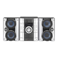
| Speaker Configuration | 2.0 |
| Tuner Bands | AM/FM |
| CD Player Type | Single Disc |
| Cassette Deck | Yes |
| Type | Mini HiFi System |
| Power Output | 100W |