Do you have a question about the Sony HCD-RG551 and is the answer not in the manual?
Details power output and total harmonic distortion for various models.
Power output and distortion for North American HCD-GX750/RX550.
Power output and distortion for HCD-RG551 and others.
Covers power requirements, consumption, dimensions, and mass.
Details FM and AM tuning ranges and intermediate frequencies.
Steps to verify safety after service.
Procedures to measure AC leakage current from metal parts.
Identifies critical components for safety.
Illustrates specific setups for accessing AMP and BD81A boards.
Lists main unit buttons and their reference pages.
Lists remote control buttons and their reference pages.
Outlines the sequential steps for disassembling the unit.
Instructions for removing the top case.
Steps for detaching the CD door.
Procedure to detach the front panel assembly.
Steps for removing the CD mechanism deck.
Procedure to switch AM channel steps between 9 kHz and 10 kHz.
Clears RAM data, returning the set to initial conditions.
Mode for checking CD and tape deck operational sequences.
Tests all fluorescent segments and LEDs, and keyboard functions.
Moves the pickup to a position safe for vibration.
Block diagram detailing the optical pickup and RF amplifier.
Block diagram showing sound processing and system control.
Block diagram of panel control and power supply circuits.
Illustrates the physical placement of main and CD mechanism boards.
Explains PCB conventions and unleaded solder usage.
Provides conventions for schematic diagrams and component values.
Shows sample waveforms for the panel board circuits.
Shows the component layout for Side A of the BD81A board.
Shows the component layout for Side B of the BD81A board.
Circuit diagram for the BD81A board components.
Component layout for LD, Driver, Sensor, and SW boards.
Circuit diagram for the driver board.
Circuit diagram for the first half of the main board.
Circuit diagram for the second half of the main board.
Shows component placement on the main board.
Shows component placement on the panel board.
Circuit diagram for the first half of the panel board.
Circuit diagram for the second half of the panel board.
Component layout for connect and stream LED boards.
Circuit diagram for the connect board.
Shows component placement on the sub woofer board.
Circuit diagram for the sub woofer board.
Component placement for the GX750/RX550 AMP board.
Component layout for the transformer section.
Circuit diagram for the GX750/RX550 AMP board.
Component placement for the RG551 AMP board.
Component layout for the RG551 transformer section.
Circuit diagram for the RG551 AMP board.
Functional diagrams for key integrated circuits like IC301, IC251.
Detailed exploded view of the main unit assembly.
Exploded view of the front panel section.
Exploded view of front panel components like cams and springs.
Exploded view of front panel parts like doors and knobs.
Exploded view showing the main board and its surrounding components.
Exploded view of the CD mechanism's main parts.
Exploded view of CD mechanism parts like gears and motors.
List of capacitors and diodes for the AMP section.
List of resistors for the AMP section.
| Brand | Sony |
|---|---|
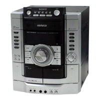
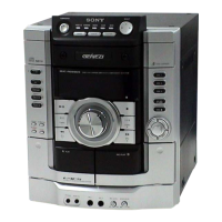
| Model | HCD-RG551 |
| Category | Stereo System |
| Language | English |