EasyManua.ls Logo

Sony HCD-RG55 User Manual

Sony HCD-RG55
74 pages
To Next Page IconTo Next Page
Page #1 background imageLoading...
Page #1 background image
1
Ver 1.1 2002. 06
Model Name Using Similar Mechanism NEW
CD
CD Mechanism Type
CDM58F-K6A
section CDM58FS-K6A
Optical Pick-up Name KSM-213DCP
Tape deck
Model Name Using Similar Machanism NEW
Section Tape Transport Mechanism Type
RG55: CWL43RR51
RG55S: CWL43FR50
SERVICE MANUAL
AEP Model
UK Model
HCD-RG55S
E Model
Australian Model
HCD-RG55
HCD-RG55/RG55S
Amplifier section
European model:
HCD-RG55S
Front speaker
DIN power output (rated)
50+50 watts (6 ohms at
1 kHz, DIN)
Continuous RMS power output (reference)
60+60 watts (6 ohms at
1 kHz, 10% THD)
Music power output (reference)
120+120 watts (6 ohms
at 1 kHz, 10% THD)
Sub woofer
DIN power output (rated)
100 watts (12 ohms at
40 Hz, DIN)
Continuous RMS power output (reference)
120 watts (12 ohms at
40 Hz, 10% THD)
Music power output (reference)
120 watts (12 ohms at
40 Hz, 10% THD)
Other models:
HCD-RG55
The following measured at AC 120, 220, 230 –
240 V, 50/60 Hz
DIN power output (rated)
100+100 watts (6 ohms
at 1 kHz, DIN)
SPECIFICATIONS
Continuous RMS power output (reference)
120+120 watts (6 ohms
at 1 kHz, 10% THD)
Inputs
MD/VIDEO (AUDIO) IN (phono jacks):
voltage 450/250 mV,
impedance 47 kilohms
GAME (AUDIO) IN (phono jack):
voltage 450 mV,
impedance 47 kilohms
MIC (phone jack) (except for European models):
sensitivity 1 mV,
impedance 10 kilohms
Outputs
PHONES (stereo mini jack):
accepts headphones of
8 ohms or more
Front speaker: accepts impedance of 6 to
16 ohms
Sub woofer speaker (MHC-RG55S only):
accepts impedance of 12
to 16 ohms
Sony Corporation
Home Audio Company
Published by Sony Engineering Corporation
9-874-003-02
2002F0400-1
© 2002. 06
– Continued on next page –
COMPACT DISC DECK RECEIVER
• HCD-RG55/RG55S is the tuner,
deck, CD and amplifier section in
MHC-RG55/RG55S.
Question and Answer IconNeed help?

Do you have a question about the Sony HCD-RG55 and is the answer not in the manual?

Sony HCD-RG55 Specifications

General IconGeneral
TypeMini Hi-Fi Component System
CD PlayerYes
TunerFM/AM
Cassette DeckYes
BluetoothNo
USB PlaybackNo
Remote ControlYes
Speakers2-way bass reflex speakers

Summary

Service Manual

Model Information

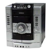
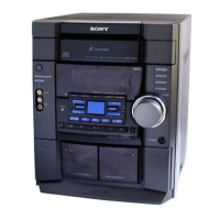
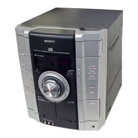
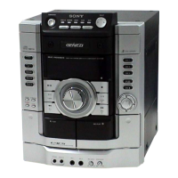
Introduces the HCD-RG55/RG55S as part of MHC-RG55/RG55S.

Specifications

Technical details including power output, inputs, and outputs.

General Specifications

Power Requirements and Consumption

Lists power requirements by region and consumption details.

Safety Cautions

Warning about hazardous radiation exposure from controls.

Component Replacement Notes

Guidance on replacing chip components and tantalum capacitors.

Handling Precautions

Optical Pick-up Handling

Precautions for handling the optical pick-up block.

Laser Diode Emission Check

Safety notes for checking laser diode emission.

Model Identification

Identifies the model via the back panel.

Service Information

Panel and Key Board Removal

Instructions for removing the panel and key boards.

Panel and Key Board Installation

Guidance for re-installing panel and key boards.

General Operations

Main Unit Controls

Alphabetical listing of main unit controls and functions.

Main Unit Button Descriptions

Descriptions of buttons on the main unit.

Remote Control Details

Remote Control Button Descriptions

Alphabetical listing of remote control buttons.

Disassembly Overview

Disassembly Overview and Flowchart

Outlines the disassembly process and order.

External Component Disassembly

Case and CD Door Removal

Procedures for removing the top case and CD door.

Front Panel Disassembly

Front Panel Section Removal

Steps for removing the front panel for different models.

Internal Mechanism Disassembly

Tape Deck and Panel Board Removal

Procedures for removing tape deck and panel boards.

Board and Keypad Disassembly

Panel Board and Key Board Removal

Steps for removing panel and key boards.

Sensor and Fan Disassembly

Sensor Board and DC Fan Removal

Procedure for disassembling sensor board and DC fan.

Core Board Disassembly

Main, Sub Woofer, Power Boards Removal

Steps for removing main, sub woofer, and power boards.

CD Board Removal

Procedure for disassembling the CD board.

Base and Supporting Board Disassembly

Base Unit and Driver/Motor Boards Removal

Steps for removing base unit and driver/motor boards.

Operational Test Modes

Cold Reset

Clears data including presets to initial conditions.

CD Ship Mode

Positions pickup for vibration resistance during shipping.

Hot Reset

Resets the set without clearing preset data.

Advanced Test Modes

MC Test Mode

Checks operations of amplifier, tuner, CD, and tape sections.

Microprocessor Version Display

Displays model name and microprocessor version numbers.

Operation Modes and Errors

Aging Mode

Used for checking CD and tape deck operations.

Error Display Codes

Explains error codes and their meanings.

Electrical Adjustment Procedures

Tuner Section Adjustments

Covers AM IF, Null, and FM Tuned Level adjustments.

AM IF Adjustment

Procedure for adjusting AM Intermediate Frequency.

Null Adjustment

Procedure for null adjustment.

CD Section Adjustment

RF Level Check

Procedure for checking RF signal level.

Circuit Board Diagrams

Circuit Boards Location

Visual guide showing the location of all circuit boards.

Printed Wiring Diagrams - CD Section 1/2

CD Board and (SPDL) Motor Board

Printed wiring layout for CD and motor boards.

Printed Wiring Diagrams - CD Section 2/2

Motor, Sensor, Driver Boards Waveforms

Displays waveforms for CD section boards.

Schematic Diagrams - CD Section

CD Section Schematic Diagram

Circuit schematic for the CD section.

Printed Wiring Diagrams - Main Section

Main Board Printed Wiring

Layout of the main board's printed wiring.

Schematic Diagrams - Main Section (1/4)

Main Section Schematic (1/4)

Circuit schematic for main section (part 1 of 4).

Schematic Diagrams - Main Section (2/4)

Main Section Schematic (2/4)

Circuit schematic for main section (part 2 of 4).

Schematic Diagrams - Main Section (3/4)

Main Section Schematic (3/4)

Circuit schematic for main section (part 3 of 4).

Schematic Diagrams - Main Section (4/4)

Main Section Schematic (4/4)

Circuit schematic for main section (part 4 of 4).

Printed Wiring Diagrams - Panel Section

Panel Board Printed Wiring

Printed wiring layout for the panel board.

Schematic Diagrams - Panel Section

Panel Section Schematic

Circuit schematic for the panel section.

Printed Wiring Diagrams - Key Section

Key Board Printed Wiring and Waveforms

Layout and waveforms for the key board.

Schematic Diagrams - Key Section

Key Section Schematic

Circuit schematic for the key section.

Printed Wiring Diagrams - Sub Woofer Section

Sub Woofer Board Printed Wiring

Printed wiring layout for the sub woofer board.

Schematic Diagrams - Sub Woofer Section

Sub Woofer Section Schematic

Circuit schematic for the sub woofer section.

Printed Wiring Diagrams - Power Section (1/3)

Power Amp Board Printed Wiring

Printed wiring layout for the power amp board.

Printed Wiring Diagrams - Power Section (2/3)

Trans Board Printed Wiring

Printed wiring layout for the trans board.

Printed Wiring Diagrams - Power Section (3/3)

Sub Trans Board Printed Wiring

Printed wiring layout for the sub trans board.

Schematic Diagrams - Power Section

Power Section Schematic

Circuit schematic for the power section.

Integrated Circuit Block Diagrams

CD Board IC Diagrams

Block diagrams for CD section ICs.

Main Board IC Block Diagrams

IC301 Main Board Block Diagram

Block diagram for IC301 on the main board.

IC102 Main Board Block Diagram

Block diagram for IC102 on the main board.

Exploded View Diagrams

Main Section Exploded View

Exploded view of the main section with part numbers.

Front Panel Exploded View

Front Panel Section Parts

Exploded view of the front panel with part details.

Main Board Exploded View

Main Board Assembly Exploded View

Exploded view of the main board assembly and related parts.

CD Mechanism Exploded View

CD Mechanism Deck Parts List

Exploded view and part list for the CD mechanism.

Optical Pick-up Exploded View

Optical Pick-up Section Parts

Exploded view and part list for the optical pick-up.

Parts List - Electrical Components

CD Components

List of electrical components for the CD section.

Service Manual Supplement Information

IC Pin Details

Detailed pin information for IC801.

Block Diagrams - CD & Tuner

CD and Tuner Section Block Diagram

Illustrates the data flow in CD and tuner sections.

Block Diagrams - Main Section

Main Section Block Diagram

Illustrates the data flow in the main section.

Related product manuals