EasyManua.ls Logo

Sony HCD-RG330 User Manual

Sony HCD-RG330
74 pages
To Next Page IconTo Next Page
Page #1 background imageLoading...
Page #1 background image
1
Ver 1.0 2003. 08
Model Name Using Similar Mechanism CX-JN3
CD Mechanism Type
CDM74F-K6BD71A
CD CDM74F-K6BD72
Section
Base Unit Name
BU-K6BD71A
BU-K6BD72
Optical Pick-up Name KSS-213DCP
Tape Deck Model Name Using Similar Machanism CX-JN3
Section Tape Transport Mechanism Type CWM43FF-13
SERVICE MANUAL
Canadian Model
HCD-GX35
AEP Model
UK Model
HCD-RG310/RG330
E Model
HCD-RG330
HCD-GX35/RG310/RG330
Amplifier section
North American models:
HCD-GX35:
Continuous RMS power output (reference):
120 + 120 watts (6 ohms at
1 kHz, 10% THD)
Total harmonic distortion less than 0.07% (6 ohms at
1 kHz, 60 W)
European models:
HCD-RG330:
DIN power output (rated): 100 + 100 watts
(6 ohms at 1 kHz, DIN)
Continuous RMS power output (reference):
120 + 120 watts (6 ohms at
1 kHz, 10% THD)
Music power output (reference):
240 + 240 watts (6 ohms at
1 kHz, 10% THD)
HCD-RG310:
DIN power output (rated): 80 + 80 watts
(6 ohms at 1 kHz, DIN)
Continuous RMS power output (reference):
100 + 100 watts (6 ohms at
1 kHz, 10% THD)
Music power output (reference):
200 + 200 watts (6 ohms at
1 kHz, 10% THD)
SPECIFICATIONS
Other models:
HCD-RG330:
The following measured at AC 120, 127, 220, 240 V,
50/60 Hz
DIN power output (rated): 100 + 100 watts
(6 ohms at 1 kHz, DIN)
Continuous RMS power output (reference):
120 + 120 watts (6 ohms at
1 kHz, 10% THD)
Inputs
GAME INPUT AUDIO L/R (phono jacks):
voltage 250 mV,
impedance 47 kilohms
GAME INPUT VIDEO (phono jack):
1 Vp-p, 75 ohms
Outputs
PHONES (stereo mini jack):
accepts headphones of
8 ohms or more
VIDEO OUT (phono jack):max. output level
1 Vp-p, unbalanced, Sync
negative, load impedance
75 ohms
SPEAKER: accepts impedance of 6 to
16 ohms
Sony Corporation
Home Audio Company
Published by Sony Engineering Corporation
9-961-223-01
2003H04-1
© 2003. 08
– Continued on next page –
COMPACT DISC DECK RECEIVER
HCD-GX35/RG310/RG330 is the
tuner, deck, CD and amplifier section
in MHC-GX35/RG310/RG330.
(Photo: HCD-GX35)
All manuals and user guides at all-guides.com
all-guides.com

Table of Contents

Question and Answer IconNeed help?

Do you have a question about the Sony HCD-RG330 and is the answer not in the manual?

Sony HCD-RG330 Specifications

General IconGeneral
CD PlayerYes
TunerAM/FM
Cassette DeckYes
USB PortNo
Remote ControlYes
Weight5.5 kg
Audio Channels2
TypeMini Hi-Fi System
Power Output100 watts

Summary

SPECIFICATIONS

Amplifier Section

Details amplifier output and characteristics for different regions.

Model Specifications Overview

Lists specifications for CD, Tape, Tuner, General, and Model Identification.

SAFETY CHECK-OUT

Leakage Test Procedures

Outlines methods for testing AC leakage current from exposed metal parts.

Handling Optical Pick-up and Laser Diode

Precautions for handling optical pick-up and checking laser diode emission.

SECTION 1 GENERAL

Main Unit and Remote Control Information

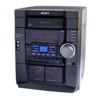
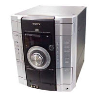
Provides general overview of the main unit and remote control functionality.

SECTION 2 DISASSEMBLY

Exterior Component Disassembly

Steps to remove the unit's top case, CD door, and front panel.

Mechanism and Board Disassembly

Procedures for removing CD/Tape mechanisms, motors, BD, and jack boards.

Internal Board Removal

Instructions for removing the main board, power amp board, SW, driver, and sensor boards.

SECTION 3 TEST MODE

System Initialization and Operational Modes

Modes for cold reset, CD shipping, CD tray lock, and tuner step change.

Diagnostic and Adjustment Modes

Modes for amplifier testing, CD error display, service, and model information.

SECTION 4 ELECTRICAL ADJUSTMENTS

S-Curve and RF Level Checks

Verifies S-curve waveform symmetry and RF signal level clarity.

SECTION 5 DIAGRAMS

IC Pin Descriptions and Block Diagrams

Details IC pin functions and block diagrams for system sections.

Circuit Board Layouts and Schematics

Covers printed wiring boards, waveforms, board locations, and detailed schematic diagrams.

SECTION 6 EXPLODED VIEWS

Main Section Exploded View

Exploded view showing the main unit's components and assembly.

Front Panel Section Exploded Views

Exploded views of front panel components, including boards, displays, and mechanisms.

CD Mechanism and Base Unit Exploded Views

Exploded views of CD mechanism deck and base unit components.

SECTION 7 ELECTRICAL PARTS LIST

REVISION HISTORY

Related product manuals