Do you have a question about the Sony HCD-RG444 and is the answer not in the manual?
Details the power output ratings for front speakers and subwoofers.
Provides specifications for the FM and AM tuner frequency ranges.
Lists specifications for the tape recording system and frequency response.
Details the CD mechanism type, laser specifications, and frequency response.
Cautionary notes regarding electrostatic breakdown and handling the optical pick-up.
Guidance on observing laser diode emission safely and precautions.
Warning for critical components identified by mark for safe operation.
Provides specific service positions for inspecting AMP and BD81A boards.
Procedure to clear all data, including preset data, to initial conditions.
Details mechanical adjustments for the tape mechanism deck section.
Provides electrical adjustments for the deck section and head azimuth.
Covers S-curve, RFAC, and RFDC level checks for the CD player.
Provides circuit board locations, waveforms, and block diagrams.
Schematics and PWBs for Main, BD/Driver, and Sub-Woofer sections.
Detailed pin functions for IC101 CXD3059AR.
Illustrates the assembly of the main unit's components.
Comprehensive list of electrical components used in the unit.
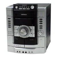
| CD Player | Yes |
|---|---|
| Cassette Deck | Yes |
| USB Port | No |
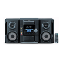
| Remote Control | Yes |
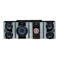
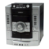
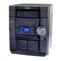
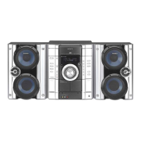
| Type | Mini Hi-Fi System |
| Tuner | AM/FM |
| Speakers | 2-Way Bass Reflex Speakers |
| MP3 Playback | Yes |