EasyManua.ls Logo

Sony HCD-RG495 User Manual

Sony HCD-RG495
86 pages
To Next Page IconTo Next Page
Page #1 background imageLoading...
Page #1 background image
SERVICE MANUAL
COMPACT DISC DECK RECEIVER
SPECIFICATIONS
HCD-RG295/RG495/RG595
Photo: HCD-RG495
Ver. 1.1 2008.09
– Continued on next page –
9-887-527-02
2008I05-1
© 2008.09
Sony Corporation
Audio&Video Business Group
Published by Sony Techno Create Corporation
AEP Model
E Model
HCD-RG295/RG495/RG595
UK Model
HCD-RG295/RG595
Australian Model
HCD-RG295/RG495
HCD-RG295 is the amplifier, CD player, tape
deck and tuner section in MHC-RG295.
HCD-RG495 is the amplifier, CD player, tape
deck and tuner section in MHC-RG495.
HCD-RG595 is the amplifier, CD player, tape
deck and tuner section in MHC-RG595.
Model Name Using Similar Mechanism HCD-RG490/RG590
CD CD Mechanism Type CDM74KF-K6BD83S
Section Base Unit Name BU-K6BD83S-WOD
Optical Pick-up Block Name KSM-213DCP
TAPE Model Name Using Similar Mechanism HCD-RG490/RG590
Section Tape Transport Mechanism Type CWN42FF609
Amplifier section
European model:
HCD-RG595
Front speaker
Power output (rated): 110 W + 110 W
(at 6 , 1 kHz, 1% THD)
RMS output power (reference): 180 W +
180 W (per channel at 6 , 1 kHz, 10%
THD)
Subwoofer
RMS output power (reference): 180 W
(at 6 , 80 Hz, 10% THD)
HCD-RG495
Front speaker
Power output (rated): 95 W + 95 W (at
6 , 1 kHz, 1% THD)
RMS output power (reference): 155 W +
155 W (per channel at 6 , 1 kHz, 10%
THD)
Subwoofer
RMS output power (reference): 155 W
(at 6 , 80 Hz, 10% THD)
HCD-RG295
Power output (rated): 95 W + 95 W (at
6 , 1 kHz, 1% THD)
RMS output power (reference): 155 W +
155 W (per channel at 6 , 1 kHz, 10%
THD)
Other models:
HCD-RG495
HCD-RG595
The following are measured at AC 120, 127,
220, 240 V 50/60 Hz
Front speaker
Power output (rated): 95 W + 95 W (at
6 , 1 kHz, 1% THD)
RMS output power (reference): 155 W +
155 W (per channel at 6 , 1 kHz, 10%
THD)
Subwoofer
RMS output power (reference): 155 W
(at 6 , 80 Hz, 10% THD)
HCD-RG295
The following are measured at AC 120, 127,
220, 240 V 50/60 Hz
Power output (rated): 95 W + 95 W (at
6 , 1 kHz, 1% THD)
RMS output power (reference): 155 W +
155 W (per channel at 6 , 1 kHz, 10%
THD)
Inputs:
AUDIO IN (stereo mini jack): voltage
250 mV, impedance 47 kilohms
Outputs:
PHONES (stereo mini jack): accepts
headphones of 8 ohms or more
SPEAKER: accepts impedance of 6 to
16 ohms
SUBWOOFER OUT (HCD-RG595/
RG495 only): accepts impedance of 6 to
16 ohms
The following are measured at AC 120, 127,
220 or 240 V, 50/60 Hz
Front speaker:
Power output (rated): 110 W + 110 W
(at 6 , 1 kHz, 1% THD)
RMS output power (reference): 180 W + 180 W
(per channel at 6 , 1 kHz, 10% THD)
Subwoofer:
RMS output power (reference): 180 W
(at 6 , 80 Hz, 10% THD)
w
w
w
.
x
i
a
o
y
u
1
6
3
.
c
o
m
Q
Q
3
7
6
3
1
5
1
5
0
9
9
2
8
9
4
2
9
8
T
E
L
1
3
9
4
2
2
9
6
5
1
3
9
9
2
8
9
4
2
9
8
0
5
1
5
1
3
6
7
3
Q
Q
TEL 13942296513 QQ 376315150 892498299
http://www.xiaoyu163.com

Table of Contents

Question and Answer IconNeed help?

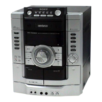
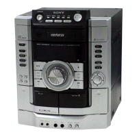
Do you have a question about the Sony HCD-RG495 and is the answer not in the manual?

Sony HCD-RG495 Specifications

General IconGeneral
BrandSony
ModelHCD-RG495
CategoryStereo System
LanguageEnglish

Summary

HCD-RG295/RG495/RG595 SERVICE MANUAL

SECTION 1 SERVICING NOTES

SECTION 3 DISASSEMBLY

Disassembly Flowchart and Steps

A visual guide outlining the sequence of disassembly steps for the unit.

SECTION 4 TEST MODE

System Reset, Ship, and Antitheft Modes

Procedures for Cold Reset, Tuning Step Change, CD Ship Lock, and Antitheft Lock modes.

Amplifier, MC, and Diagnostic Test Modes

Instructions for AMP Test Mode, MC Test Mode, Version Display, and CD Error Code Display.

SECTION 5 MECHANICAL ADJUSTMENTS

Precautions and Measurement Procedures

Important preliminary steps and specifications for torque and tape tension measurements.

SECTION 6 ELECTRICAL ADJUSTMENTS

Deck Section and FM Tune Adjustments

Procedures for demagnetizing heads and adjusting record/playback head azimuth.

FM Tune Level and Focus Bias Checks

Methods for checking FM signal reception and optical pick-up focus bias.

SECTION 7 DIAGRAMS

CD Servo Section Block Diagram

Schematic showing the signal flow and components within the CD servo system.

Main Section Block Diagram (1/3)

Overview of signal paths and major blocks in the main audio processing section.

Amplifier/Video Section Block Diagram

Schematic illustrating the amplifier, protection, and fan control circuitry.

Panel/Power Supply Section Block Diagram

Diagram showing the power supply distribution and panel control interface.

CD Board Schematic Diagram

Detailed schematic showing the CD DSP IC, optical pick-up interface, and related circuits.

Changer Section Schematic Diagram

Detailed schematic of the driver board ICs controlling the changer mechanism components.

Deck Board Schematic Diagram

Detailed schematic of the deck board's audio playback and recording circuits, including ICs.

Main Section Schematic Diagram (1/3)

Detailed schematic of the main board, showing input/output signals and system controller IC.

Main Section Schematic Diagram (2/3)

Detailed schematic of the main board's audio processing ICs, including equalization and volume control.

Main Section Schematic Diagram (3/3)

Detailed schematic of the main board's power management and protection circuits.

Panel and Key Section Schematics

Detailed schematics for the panel board and associated key boards, showing button and display controls.

Power Board (RG295/495) Schematic Diagram

Detailed schematic of the power board for RG295/RG495, including amplifier and protection circuits.

Power Board (RG595) Schematic Diagram

Detailed schematic of the power board for RG595, including amplifier and protection circuits.

Sub Woofer Section Schematic Diagram

Detailed schematic of the sub woofer amplifier circuit, including IC and protection components.

Transformer Board (RG295/495) Schematic Diagram

Detailed schematic of the transformer board for RG295/RG495, showing power supply and voltage selection.

SECTION 8 EXPLODED VIEWS

SECTION 9 ELECTRICAL PARTS LIST

Related product manuals