Do you have a question about the Sony HCD-RG470 and is the answer not in the manual?
Guidelines for safely handling the optical pick-up block and flexible circuit boards during repair.
Procedure for safely checking the laser diode emission, emphasizing safe viewing distance.
Information on identifying different models based on label indications found on the back panel.
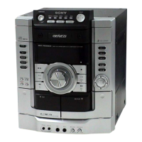
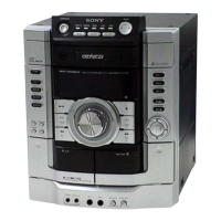
Details on the location and function of controls on the main unit of the HCD-GX255/RG170/RG470.
Diagram and description of buttons and their functions on the remote control.
Step-by-step guide illustrating the sequence for disassembling the HCD-GX255/RG170/RG470 unit.
Instructions for safely removing the top case and the CD door assembly.
Procedures for removing the front panel section and the mechanical CD deck assembly.
Steps to access and remove the main board, BD/CD board, and driver/SW boards.
Clears all preset data to initial conditions, used when returning the set to the customer.
Displays amplifier IC parameters and VACS status for adjustment purposes.
Moves the optical pick-up to a vibration-durable position for customer return.
Enables display of mechanism deck and optical pick-up error codes for troubleshooting.
Procedure to check the symmetry and peak-to-peak level of the S-curve waveform.
Procedure to confirm the clarity and correctness of the RFAC signal waveform.
Overview of the CD servo system's signal paths and component interactions.
Diagram illustrating the signal flow and components within the amplifier section.
Schematic representation of the power supply section, including transformers and regulators.
Layout of components and traces on the CD board (component and conductor sides).
Schematic representation of the MAIN board, covering its internal circuitry and connections.
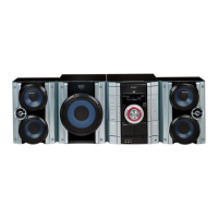
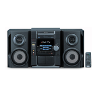
Diagram showing the main external components of the HCD-GX255/RG170/RG470 set.
Detailed breakdown of the front panel components, including knobs, buttons, and displays.
Exploded view of the internal chassis, showing the layout of main boards and transformers.
List of capacitors with part numbers, descriptions, and electrical values.
List of resistors with part numbers, descriptions, and electrical values.
List of integrated circuits with part numbers, descriptions, and pin functions.
Initial release of the service manual.
Added part numbers for specific exploded view references.
Updates to CD mechanism, main, and headphone boards, including destination changes.
| Brand | Sony |
|---|---|
| Model | HCD-RG470 |
| Category | Stereo System |
| Language | English |