73
HCD-SB100/SB200
Ver. 1.1
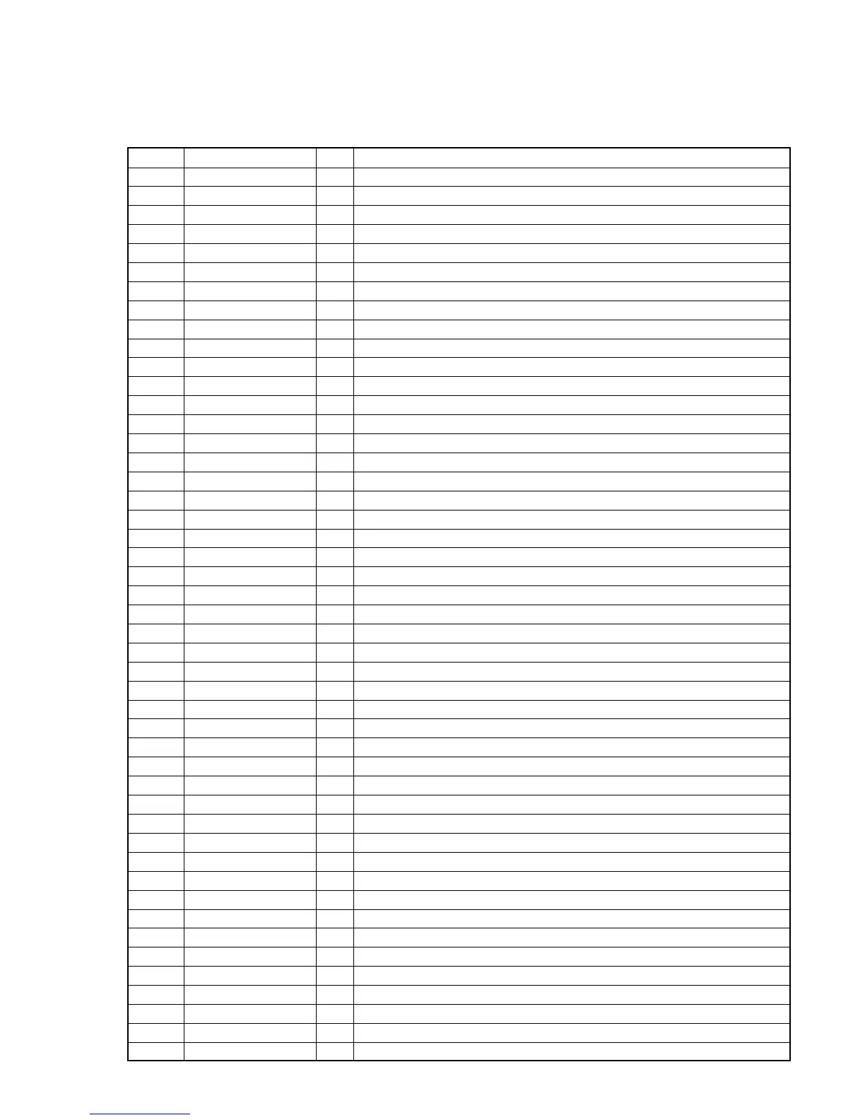
• IC Pin Function Description
AMP BOARD IC101 LC87684C-54C7 (SYSTEM CONTROLLER)
Pin No. Pin Name I/O Description
1DVD_RESET O Reset signal output to DVD
2 P_CTL O Power control signal output
3DVD_CE O CE signal to DVD
4 /STEREO I Stereo signal output from the tuner
5 T_CE O CE signal output to the tuner
6 T_RDS_DATA O RDS DATA to the tuner
7 T_CLK O Clock signal to the tuner
8T.DO O DATA output to the tuner
9 T_DI I DATA input from the tuner
10 T_RDS_CLK O RDS clock to the tuner
11 RESET I Reset signal input
12 XT1 — Not used
13 XT2 — Not used
14 VSS1 — Ground terminal
15 CF1 — Resonator terminal(9.8304MHz)
16 CF2 — Resonator terminal(9.8304MHz)
17 VDD1 — Power suply terminal(+5V)
18 KEY1 I Key AD input1
19 KEY2 I Key AD input2(Not used)
20 VOL_UP I Volume up input(Not used)
21 VOL_DN I Volume down input(Not used)
22 4052A O Signal output to the Selector_A
23 4052B O Signal output to the Selector_B
24 HP_DET I Detect signal input from the Headphone
25 HP_MUTE O Muting signal output to the Headphone
26 PWRSNS I Sense signal from Vdd
27 STBY_LED O Standby LED control signal output
28 NC — Not used
29 REMOCON I Input signal from the REMOCON
30 to 40 G1 to G11 O Segment signal output to the fluorescent indicator tube
41 to 45 P17 to P13 O Segment signal output to the fluorescent indicator tube
46 VDD3 — Power suply terminal(+5V)
47 to 50 P12 to P9 O Segment signal output to the fluorescent indicator tube
51 VP — Power suply terminal(-28.5V)
52 to 59 P8 to P1 O Segment signal output to the fluorescent indicator tube
60 NC60 — Not used
61 NC61 — Not used
62 NC62 — Not used
63 NC63 — Not used
64 OPTION I Option terminal
65 NC65 — Not used
66 NC66 — Not used
67 NC67 — Not used
68 MICDET2 — Detect signal from the microphone(Not used)
69 MICDET1 — Detect signal from the microphone(Not used)
70 501/505_TH_WAR I Thermal warning advisor signal Input from the Audio Amp
71 501/505_FAULT O Fault pin advisor signal output to the Audio Amp


 To Next Page