Do you have a question about the Sony HCD-T1 and is the answer not in the manual?
Step-by-step guide for removing the front panel assembly.
Procedure for detaching the back panel section from the unit.
Instructions for safely removing the CD mechanism.
Provides the main electrical schematic diagram for the unit.
Provides the electrical schematic diagram for the BD section.
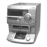
| CD Player | Yes |
|---|---|
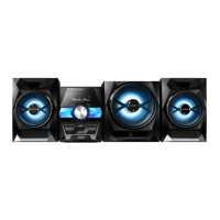
| Output Power | 25W per channel |
| Type | Mini Hi-Fi System |
| Tuner | AM/FM |
| Cassette Deck | Yes |
| Speakers | Yes |