SERVICE MANUAL
Sony Corporation
Audio&Video Business Group
Published by Sony Techno Create Corporation
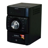
HCD-EC59
SPECIFICATIONS
COMPACT DISC RECEIVER
9-889-885-01
2010F05-1
©
2010.06
E Model
Ver. 1.0 2010.06
• HCD-EC59 is the amplifi er, USB, CD player and
tuner section in MHC-EC59.
Model Name Using Similar Mechanism HCD-EX6/EX6T
Base Unit Name BU-D1BD74UR
Optical Pick-up Block Name DA11MMVGP
• MPEG Layer-3 audio coding technology and patents licensed from Fraunhofer IIS and Thomson.
• Windows Media is either a registered trademark or trademark of Microsoft Corporation in the
United States and/or other countries.
• This product is protected by certain intellectual property rights of Microsoft Corporation. Use or
distribution of such technology outside of this product is prohibited without a license from Micro-
soft or an authorized Microsoft subsidiary.
Main unit
Amplier section
e following measured at AC 127 V, 60 Hz
(Mexican model)
e following measured at AC 220 V,
50/60 Hz (Argentine model)
e following measured at AC 120 V, 220 V,
240 V, 50/60 Hz (Other models)
Power output (rated):
25 W + 25 W (at 6 Ω, 1 kHz, 1%
THD)
RMS output power (reference):
60 W + 60 W (per channel at 6 Ω,
1 kHz)
Inputs
PC IN (stereo mini jack):
Sensitivity 800 mV, impedance
22 kilohms
Outputs
PHONES (stereo mini jack):
accepts headphones with an
impedance of 8 Ω or more
SPEAKERS: impedance: 6 Ω
USB section
Supported bit rate:
MP3 (MPEG 1 Audio Layer-3):
32 kbps – 320 kbps, VBR
WMA: 48 kbps – 192 kbps
AAC: 48 kbps – 320 kbps
Sampling frequencies:
MP3 (MPEG 1 Audio Layer-3):
32/44.1/48 kHz
WMA: 44.1 kHz
AAC: 44.1 kHz
(USB) port:
Maximum current:
500 mA
CD player section
System:
Compact disc and digital audio
system
Laser Diode Properties
Emission Duration: Continuous
Laser Output*: Less than 44.6μW
* is output is the value
measurement at a distance of
200mm from the objective lens
surface on the Optical Pick-up Block
with 7mm aperture.
Frequency response: 20 Hz – 20 kHz
Signal-to-noise ratio: More than 90 dB
Dynamic range: More than 88 dB
Tuner section
FM stereo, FM/AM superheterodyne tuner
Antenna:
FM lead antenna
AM loop antenna
FM tuner section:
Tuning range:
87.5 MHz – 108.0 MHz (50 kHz step)
Intermediate frequency: 225 kHz
AM tuner section:
Tuning range
Latin American models:
530 kHz – 1,710 kHz (10 kHz step)
531 kHz – 1,710 kHz (9 kHz step)
Other models:
531 kHz – 1,602 kHz (9 kHz step)
530 kHz – 1,610 kHz (10 kHz step)
Intermediate frequency: 53 kHz
General
Power requirements
Mexican model:
AC 127 V, 60 Hz
Argentine model:
AC 220 V, 50/60 Hz
Other models:
AC 120 V, 220 V or 230 V 240 V,
50/60 Hz, adjustable with voltage
selector
Power consumption: 85 W
(0.5 Wat the Power Saving Mode)
Dimensions (W/H/D) (excl. speakers)
Approx. 200 mm × 306 mm ×
305 mm
Mass (excl. speakers): Approx. 3.8 kg
Design and specications are subject to
change without notice.
Standby power consumption: 0.5 W
Halogenated ame retardants are not used
in the certain printed wiring boards.