EasyManua.ls Logo

Sony HCD-CBX3 Service Manual

Sony HCD-CBX3
76 pages
To Next Page IconTo Next Page
Page #1 background imageLoading...
Page #1 background image
SERVICE MANUAL
COMPACT DISC RECEIVER
SPECIFICATIONS
HCD-BX5BT/CBX1/CBX3
Photo: HCD-BX5BT
Ver. 1.0 2007.03
– Continued on next page –
9-887-614-01
2007C05-1
© 2007.03
Sony Corporation
Personal Audio Division
Published by Sony Techno Create Corporation
US Model
HCD-BX5BT/CBX1
AEP Model
UK Model
HCD-CBX3
HCD-BX5BT is the amplifier, bluetooth, CD player
and tuner section in CMT-BX5BT.
HCD-CBX1 is the amplifier, CD player and tuner
section in CMT-BX1
HCD-CBX3 is the amplifier, USB, CD player and
tuner section in CMT-BX3.
Model Name Using Similar Mechanism NEW
Base Unit Name
HCD-BX5BT/CBX1 BU-K6BD90-WOD
HCD-CBX3 BU-K6BD90U-WOD
Optical Pick-up Block Name KSM-213DCP
•“WALKMAN” and “WALKMAN” logo are registered
trademarks of Sony Corporation.
MICROVAULT is a trademark of Sony Corporation.
•ATRAC, ATRAC3, ATRAC3plus and their logos are
trademarks of Sony Corporation.
U.S. and foreign patents licensed from Dolby
Laboratories.
MPEG Layer-3 audio coding technology and patents
licensed from Fraunhofer IIS and Thomson.
AUDIO POWER SPECIFICATIONS POWER OUTPUT
AND TOTAL HARMONIC DISTORTION (BX5BT/
CBX1):
With 6 ohm loads, both channels driven, from 120 –
10,000Hz; rated 12 watts per channel minimum RMS
power, with no more than 10% total harmonic distortion
from 250 milliwatts to rated output.
Amplifier section
BX5BT/CBX1:
Continuous RMS power output
(reference): 15 + 15 watts (6 ohms at 1 kHz, 10%
THD)
Inputs:
AUDIO IN (stereo mini jack):
voltage 250 mV, impedance 47 kilohms
Outputs:
PHONES (stereo mini jack): accepts he/adphones of
8 ohms or more
SPEAKER: accepts impedance of 6 to 16 ohms
CBX3:
DIN power output (rated):
18 + 18 watts (6 ohms at 1 kHz, DIN)
Continuous RMS power output
(reference): 25 + 25 watts (6 ohms at 1 kHz, 10%
THD)
Music power output (reference):
38 + 38 watts (6 ohms at 1 kHz, 10% THD)
Inputs:
AUDIO IN (stereo mini jack):
voltage 250 mV, impedance 47 kilohms
(USB) port: Type A, maximum current 500 mA
Outputs:
PHONES (stereo mini jack): accepts headphones of
8 ohms or more
SPEAKER: accepts impedance of 6 to 16 ohms
Bluetooth section (BX5BT)
Communication system:
Bluetooth Standard version 2.0
Output:
Bluetooth Standard Power Class 2
Maximum communication range:
Line of sight approx. 10 m
1)
Frequency band:
2.4 GHz band (2.4000 GHz – 2.4835 GHz)
Modulation method:
FHSS
Compatible Bluetooth profiles
2)
:
A2DP (Advanced Audio Distribution Profile)
AVRCP (Audio Video Remote Control Profile)
Supported codecs:
Receive: SBC (Sub Band Codec), MP3
Transmit: SBC (Sub Band Codec)
1)
The actual range will vary depending on factors such
as obstacles between devices, magnetic fields around
a microwave oven, static electricity, reception
sensitivity, antenna’s performance, operating system,
software application, etc.
2)
Bluetooth standard profiles indicate the purpose of
Bluetooth communication between devices.
USB section (CBX3)
Supported bit rate
MP3 (MPEG 1 Audio Layer-3):
32 – 320 kbps, VBR
ATRAC: 48 – 352 kbps
(ATRAC3plus), 66/105/132 kbps
(ATRAC3)
WMA: 32 – 192 kbps, VBR
AAC: 48 – 320 kbps
Sampling frequencies
MP3 (MPEG 1 Audio Layer-3):
32/44.1/48 kHz
ATRAC: 44.1 kHz
WMA: 44.1 kHz
AAC: 44.1 kHz
CD player section
System: Compact disc and digital audio
system
Laser Diode Properties
Emission duration: continuous
Laser Output*: Less than 44.6µ W
*This output is the value measurement at a distance
of 200mm from the objective lens surface on the
Optical Pick-up Block with 7mm aperture.
Frequency response: 20 Hz – 20 kHz
Signal-to-noise ratio: More than 90 dB
Dynamic range: More than 90 dB

Table of Contents

Question and Answer IconNeed help?

Do you have a question about the Sony HCD-CBX3 and is the answer not in the manual?

Sony HCD-CBX3 Specifications

General IconGeneral
TypeMini Hi-Fi System
CD PlaybackYes
Power Output50 W
BluetoothNo
USB PlaybackYes
Cassette DeckYes
Output Power50 W
Remote ControlYes
Supported Disc TypesCD, CD-R, CD-RW
Signal-to-Noise Ratio80 dB
Radio TunerAM/FM
Speaker Configuration2.0
FunctionsCD, Radio

Summary

SPECIFICATIONS

AUDIO POWER SPECIFICATIONS

Power output and total harmonic distortion for BX5BT/CBX1.

Amplifier section

Details of continuous RMS power output and input/output for amplifier.

USB section (CBX3)

Supported bit rates, sampling frequencies for USB playback.

Bluetooth section (BX5BT)

Communication system, range, frequency band, and profiles.

CD player section

System type, laser diode properties, frequency response, SNR, dynamic range.

SECTION 1 SERVICING NOTES

Notes on chip component replacement

Precautions for replacing chip components, especially tantalum capacitors.

Flexible Circuit Board Repairing

Guidelines for soldering and handling flexible circuit boards.

CAUTION

Warning regarding hazardous radiation exposure from controls or procedures.

SAFETY-RELATED COMPONENT WARNING!!

Warning about critical components identified by mark for safe operation.

SAFETY CHECK-OUT

Procedure to ensure the set is safe before returning it to the customer.

LEAKAGE TEST

Procedure to measure AC leakage current from exposed metal parts to earth ground.

NOTES ON HANDLING THE OPTICAL PICK-UP BLOCK OR BASE UNIT

Precautions for handling optical pick-up blocks and flexible boards.

NOTES ON LASER DIODE EMISSION CHECK

Instructions for safely checking laser diode emission.

UNLEADED SOLDER

Characteristics and handling of unleaded solder.

ANTITHEFT UNLOCK MODE

Procedure to unlock the disc tray.

HOW TO OPEN THE TRAY WHEN POWER SWITCH TURN OFF

Method to open the disc tray without the unit powered on.

SECTION 2 GENERAL

HCD-BX5BT: Guide to parts and controls

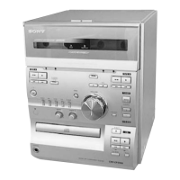
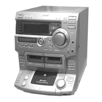
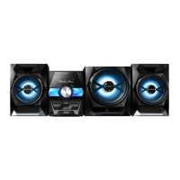
Identification and function of unit and remote controls for HCD-BX5BT.

Setting the clock

Step-by-step guide to set the system clock using the remote.

HCD-BX1: Basic Operations

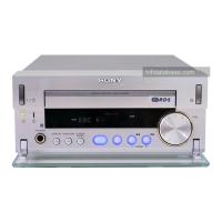
Basic operations for HCD-BX1, including sound adjustment and radio tuning.

Adjusting the sound

How to adjust volume and add sound effects like DSGX and EQ.

Listening to the radio

Procedure for tuning FM/AM stations, including auto and manual tuning.

Playing a CD/MP3 disc

Steps for selecting CD function, playing discs, and basic playback controls.

Changing the display

How to change information displayed on the system unit.

Using optional audio components

Instructions for connecting headphones and other audio components.

Other Operations

Advanced operations such as program play, radio presets, and timers.

Creating your own program (Program Play)

Method to create a custom program of tracks or files for playback.

Presetting radio stations

Guide to storing and recalling favorite radio stations using preset numbers.

Using the Timers

Instructions for setting Sleep Timer and Play Timer functions.

HCD-BX3: Guide to parts and controls

Identification and function of unit and remote controls for HCD-BX3.

Setting the clock

Step-by-step guide to set the system clock using the remote.

SECTION 3 DISASSEMBLY

DISASSEMBLY FLOW

Step-by-step procedure for disassembling the set.

PANEL (SIDE L/R)

Procedure for removing side panels.

PANEL (TOP)

Procedure for removing the top panel.

MAIN BOARD, SHIELD PLATE (PWB MAIN)

Procedure for accessing and removing the main board and shield plate.

BT BOARD (BX5BT only)

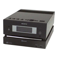
Procedure for removing the Bluetooth board specific to BX5BT models.

LID (CD) ASSY

Procedure for removing the CD lid assembly.

PANEL (FRONT) ASSY

Procedure for removing the front panel assembly.

D.C. FAN (M301), PANEL (REAR)

Procedure for removing the DC fan and rear panel.

POWER TRANSFORMER (T1)

Procedure for removing the power transformer.

LOADING MECHANISM BLOCK

Procedure for removing the loading mechanism block.

BASE UNIT

Procedure for accessing and removing the base unit.

BELT

Procedure for accessing and replacing the drive belt.

OP BASE ASSY (KSM-213D)

Procedure for removing the optical pick-up base assembly.

SECTION 4 TEST MODE

COLD RESET

Procedure to reset all stored data to initial conditions.

COMMON TEST MODE

Mode for checking amplifier operations and sound effect settings.

PANEL TEST MODE

Mode for checking LCD, LEDs, model, destination, and key functions.

TUNER STEP CHANGE (BX5BT/CBX1)

Procedure to change AM tuning interval between 9 kHz and 10 kHz.

CD SHIP MODE

Mode to move optical pick-up to a vibration-resistant position.

CD SHIP MODE & MEMORY CLEAR

Combined mode for CD ship mode and cold reset.

ANTITHEFT LOCK MODE

Mode to prevent sample disc removal from the tray.

CD POWER MANAGE

Mode to change CD power on/off for reducing reception noise.

CD SERVICE MODE

Mode to freely run the CD sled motor, useful for cleaning.

BT TEST MODE (BX5BT)

Mode to check firmware version and address of the Bluetooth module.

SECTION 5 ELECTRICAL CHECKS

TUNER SECTION

Procedures for checking tuner performance and signal reception.

FM TUNE LEVEL CHECK

Procedure to check FM signal reception levels and tuning indicators.

CD SECTION

Procedures for checking CD playback performance.

FOCUS BIAS CHECK

Procedure to check CD focus bias using an oscilloscope.

SECTION 6 DIAGRAMS

BLOCK DIAGRAM - CD SERVO Section -

Block diagram illustrating the CD servo system.

BLOCK DIAGRAM - TUNER, USB, BLUETOOTH Section -

Block diagram for tuner, USB, and Bluetooth signal paths.

BLOCK DIAGRAM - MAIN Section -

Block diagram showing the main functional blocks and connections.

BLOCK DIAGRAM - PANEL, POWER SUPPLY Section -

Block diagram illustrating panel and power supply sections.

PRINTED WIRING BOARDS - CD Section

Layout of the CD board's printed wiring.

SCHEMATIC DIAGRAM - CD Board -

Schematic diagram of the CD board components and connections.

PRINTED WIRING BOARD - USB Board (CBX3) -

Layout of the USB board's printed wiring for CBX3 model.

SCHEMATIC DIAGRAM - USB Board (CBX3) -

Schematic diagram of the USB board's components and connections for CBX3.

PRINTED WIRING BOARDS - BLUETOOTH Section (BX5BT) -

Layout of the Bluetooth board's printed wiring for BX5BT model.

SCHEMATIC DIAGRAM - BLUETOOTH Section (BX5BT) -

Schematic diagram of the Bluetooth board's components and connections for BX5BT.

PRINTED WIRING BOARDS - REGULATOR Section -

Layout of the regulator boards' printed wiring.

SCHEMATIC DIAGRAM - REGULATOR Section -

Schematic diagram of the regulator boards' components and connections.

PRINTED WIRING BOARD - MAIN Board -

Layout of the main board's printed wiring.

SCHEMATIC DIAGRAM - MAIN Section (1/4) -

First part of the main section schematic diagram.

SCHEMATIC DIAGRAM - MAIN Section (2/4) -

Second part of the main section schematic diagram.

SCHEMATIC DIAGRAM - MAIN Section (3/4) -

Third part of the main section schematic diagram.

SCHEMATIC DIAGRAM - MAIN Section (4/4) -

Fourth part of the main section schematic diagram.

PRINTED WIRING BOARD - AMP Board -

Layout of the amplifier board's printed wiring.

SCHEMATIC DIAGRAM - AMP Board -

Schematic diagram of the amplifier board's components and connections.

PRINTED WIRING BOARDS - SPEAKER Section -

Layout of the speaker board's printed wiring.

SCHEMATIC DIAGRAM - SPEAKER Section -

Schematic diagram of the speaker board's components and connections.

PRINTED WIRING BOARDS - PANEL Section -

Layout of the front and top panel boards' printed wiring.

SCHEMATIC DIAGRAM - PANEL Section -

Schematic diagram of the panel boards' components and connections.

PRINTED WIRING BOARD - POWER Board -

Layout of the power board's printed wiring.

SCHEMATIC DIAGRAM - POWER Board -

Schematic diagram of the power board's components and connections.

SECTION 7 EXPLODED VIEWS

PANEL SECTION

Exploded view of the set's panel components.

FRONT PANEL SECTION

Exploded view detailing front panel components.

MAIN SECTION

Exploded view of the main internal sections of the unit.

POWER BOARD SECTION

Exploded view illustrating power board components and their locations.

LOADING MECHANISM SECTION

Exploded view of the disc loading mechanism.

BASE UNIT SECTION

Exploded view of the base unit, including optical pick-up.

SECTION 8 ELECTRICAL PARTS LIST

5V REGULATOR AMP

List of electrical parts for the 5V regulator and amplifier sections.

AMP BOARD

List of electrical parts for the amplifier board.

AMP ANT BT

List of electrical parts for amplifier, antenna, and Bluetooth boards.

TOP PANEL USB

List of electrical parts for top panel and USB interface.

CD

List of electrical parts for the CD board.

CD FRONT PANEL HEADPHONE

List of electrical parts for CD, front panel, and headphone sections.

HEADPHONE MAIN

List of electrical parts for headphone and main boards.

MAIN

List of electrical parts for the main board.

MAIN

List of electrical parts for the main board.

MAIN MOTOR POWER

List of electrical parts for main, motor, and power sections.

MAIN MOTOR POWER

List of electrical parts for main, motor, and power sections.

POWER REGULATOR SPEAKER TOP PANEL

List of electrical parts for power, regulator, speaker, and top panel.

TOP PANEL USB

List of electrical parts for top panel and USB interface.

USB

List of electrical parts for the USB interface.

Related product manuals