EasyManua.ls Logo

Sony HCD-XB50 User Manual

Sony HCD-XB50
88 pages
To Next Page IconTo Next Page
Page #1 background imageLoading...
Page #1 background image
HCD-D390/D790/G5500/
XB33/XB44/XB50/XB60
SERVICE MANUAL
COMPACT DISC DECK RECEIVER
MICROFILM
Model Name Using Similar Mechanism HCD-D290/
G3300/XB3
CD Mechanism Type CDM37L-5BD29AL
Base Unit Name BU-5BD29AL
Optical Pick-up Name KSS-213D/Q-NP
Model Name Using Similar Mechanism HCD-D290/
G3300/XB3
Tape Transport Mechanism Type TCM-220WR2
HCD-D390/D790/G5500/XB33/XB44/
XB50/XB60 is the tuner, deck, CD and
amplifier section in LBT-D390/D790/G5500/
XB33/XB44/XB50/XB60
.
— Continued on next page —
SPECIFICATIONS
US Model
HCD-D390/D790/G5500
Canadian Model
HCD-390/D790
AEP Model
UK Model
HCD-XB50/XB60
E Model
Australian Model
HCD-XB33/XB44
Photo: HCD-XB44
For the U.S. model
AUDIO POWER SPECIFICATIONS
POWER OUTPUT AND TOTAL HARMONIC DISTORTION:
With 8 ohm loads, both channels driven, from 70-20,000 Hz; rated 100
watts per channel minimum RMS power, with no more than 0.9 % total
harmonic distortion from 250 milliwatts to rated output.
Amplifier section
(HCD-D390/D790/G5500)
Continuous RMS power output:
120 + 120 watts (8 ohms at 1 kHz, 10% THD)
Total harmonics distortionm:
Less than 0.07% (8 ohms at 1 kHz, 50 W)
(HCD-XB50)
DIN power output (Rated):80 + 80 watts (8 ohms at 1 kHz, DIN)
Continuous RMS power output (Reference):
100 + 100 watts (8 ohms at 1 kHz, 10% THD)
Music power output (Reference):
170 + 170 watts (8 ohms at 1 kHz, 10% THD)
(HCD-XB60)
DIN power output (Rated):
100 + 100 watts (8 ohms at 1 kHz, DIN)
Continuous RMS power output (Reference):
120 + 120 watts (8 ohms at 1 kHz, 10% THD)
Music power output (Reference):
210 + 210 watts (8 ohms at 1 kHz, 10% THD)
(HCD-XB33)
The following measured at AC 120/240 V, 50 Hz
DIN power output (Rated):
100 + 100 watts (6 ohms at 1 kHz, DIN)
Continuous RMS power output (Reference):
120 + 120 watts
(6 ohms at 1 kHz, 10% THD)
Peak music power potput (Reference):
1,500 watts
(HCD-XB44)
The following measured at AC 120/240 V, 50 Hz
DIN power output (Rated):
120 + 120 watts (6 ohms at 1 kHz, DIN)
Continuous RMS power output (Reference):
140 + 140 watts
(6 ohms at 1 kHz, 10% THD)
Peak music power output (Reference):
2,000 watts
*Dolby noise reduction manufactured under license
from Dolby Laboratories Licensing Corporation.
“DOLBY” and the double-D symbol a are
trademarks of the Dolby Laboratories Licensing
Corporation.
CD
Section
Tape Deck
Section
w
w
w
.
x
i
a
o
y
u
1
6
3
.
c
o
m
Q
Q
3
7
6
3
1
5
1
5
0
9
9
2
8
9
4
2
9
8
T
E
L
1
3
9
4
2
2
9
6
5
1
3
9
9
2
8
9
4
2
9
8
0
5
1
5
1
3
6
7
3
Q
Q
TEL 13942296513 QQ 376315150 892498299
http://www.xiaoyu163.com
Question and Answer IconNeed help?

Do you have a question about the Sony HCD-XB50 and is the answer not in the manual?

Sony HCD-XB50 Specifications

General IconGeneral
Speaker Type2-Way Bass Reflex
BluetoothNo
USB PlaybackNo
FM TunerYes
CD PlayerYes
TunerFM/AM
Cassette DeckNo
Power Output50 W
FunctionsCD, Radio
Speakers2
TypeMini Hi-Fi System

Summary

Specifications

Audio Power Specifications

Details audio power output and total harmonic distortion for amplifier sections.

CD Player Section

Specifies parameters for the CD player, including laser and output characteristics.

Tape Deck Section

Details recording system, laser, and frequency response for the tape deck.

Tuner Section

Outlines specifications for FM and AM tuner sections, including tuning ranges.

General Specifications

Power Requirements

Lists voltage and frequency requirements for different regions.

Safety Check-out Procedures

Leakage Test

Details AC leakage testing procedures and limits for exposed metal parts.

Servicing Notes

Handling Optical Pick-up Block or Base Unit

Precautions for handling optical pick-up block and base unit due to electrostatic discharge.

Laser Diode Emission Check

Guidelines for safely checking laser diode emission from the optical pick-up block.

Diagrams Overview

Block Diagrams

Provides high-level functional block diagrams for key sections like CD, Tuner, and Main.

Section 1 General

Front Panel Overview

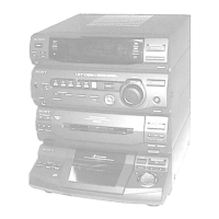
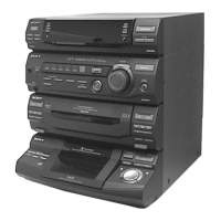
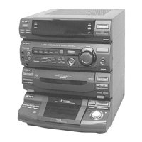
Identifies and labels components and controls on the front panel of the unit.

Back Panel Overview

Identifies and labels connectors and switches located on the rear panel of the unit.

Section 2 Disassembly

Upper Case Removal

Details the procedure for removing the upper case of the unit, including screw points.

Front Panel Section Removal

Describes the steps for detaching the front panel assembly from the main unit.

Section 3 Test Mode

MC Cold Reset

Clears all preset data in RAM to initial conditions, used when returning the set to the customer.

CD Delivery Mode

Moves the pickup to a position durable to vibration for shipping or post-repair return.

MC Hot Reset

Resets the set with preset data stored in memory, functioning like power cord unplug/replug.

Sled Servo Mode

Allows free movement of the CD sled motor, useful for cleaning the pickup.

AM Tuner Step Change-over

Toggles AM channel step between 9kHz and 10kHz.

Aging Mode Operations

Aging Mode in CD Section

Details procedures for activating and operating the aging mode for the CD section.

Aging Mode in Tape Deck Section

Explains how to activate and operate the aging mode for the tape deck sections.

Section 4 Mechanical Adjustments

Section 5 Electrical Adjustments

Deck Section Adjustments

Covers azimuth and tape speed adjustments for deck sections.

Tape Speed Adjustment

Details high and normal speed adjustments for tape decks using a frequency counter.

Playback Level Adjustment

Outlines the procedure for adjusting playback level using a level meter and test tape.

Record Bias Current Adjustment

Explains how to adjust bias current for DECK B using an oscilloscope and level meter.

Record Level Adjustment

Details the process for adjusting record level for DECK B using an oscilloscope.

Tuner Section Adjustments

Details AM, FM, and FM Polar level adjustments for tuner sections.

FM Polar Adjustment (East European, CIS model only)

Describes FM polar adjustment procedure for East European and CIS tuner models.

CD Section Adjustments

Covers focus bias and RF level checks for the CD section, using an oscilloscope.

E-F Balance (1) Track Jump) Check

Details the procedure for checking E-F balance and track jump in the CD section.

Section 6 Diagrams

Circuit Board Location

Illustrates the physical placement of various circuit boards within the unit.

IC Pin Function Description - Main Board IC301

Details the function of each pin for the µPD780018Y integrated circuit on the main board.

IC Pin Function Description - Main Board IC301 (Continued)

Lists pin functions for IC301 from pin 51 to 100, covering various controls and signals.

IC Pin Function Description - Panel Board IC601

Details the function of each pin for the TMP87CH74 integrated circuit controlling the display.

Section 7 Exploded Views

Section 8 Electrical Parts List

Related product manuals