EasyManua.ls Logo

Sony HCD-XB66 User Manual

Sony HCD-XB66
78 pages
To Next Page IconTo Next Page
Page #1 background imageLoading...
Page #1 background image
MICROFILM
SERVICE MANUAL
COMPACT DISC DECK RECEIVER
E Model
Australian Model
HCD-XB66
Mexican Model
HCD-XB660
SPECIFICATIONS
HCD-XB66/XB660
HCD-XB66, HCD-XB660 are the tuner,
deck, CD and amplifier section in LBT-
XB66, LBT-XB660.
Dolby noise reduction manufactured under license
from Dolby Laboratories Licensing Corporation.
“DOLBY” and the double-D symbol a are trade-
marks of Dolby Laboratories Licensing Corporation.
Model Name Using Similar Mechanism HCD290/G330/XB3
CD Mechanism Type CDM37LH-5BD29AL
Base Unit Name BU-5BD29AL
Optical Pick-up Name KSS-213D/Q-NP
Model Name Using Similar Mechanism HCD-H881
Tape Transport Mechanism Type TCM-220WR2
CD
Section
Tape deck
Section
Amplifier section
The following measured at AC 120/240 V, 50 Hz
DIN power output (Rated) 140 + 140 watts
(8 ohms at 1 kHz, DIN)
Continuous RMS power output (Reference)
170 + 170 watts
(8 ohms at 1 kHz, 10% THD)
Peak music power output (Reference)
3,000 watts
Inputs
PHONO IN (phono jacks): sensitivity 3 mV, impedance
47 kilohms
MIX MIC (phone jack): sensitivity 1 mV, impedance
10 kilohms
VIDEO/MD (AUDIO) IN (phono jacks):
sensitivity 250 mV, impedance
47 kilohms
Outputs
PHONES (stereo phone jack): accepts headphones of 8 ohms or more
VIDEO/MD (AUDIO) OUT (phono jacks):
voltage 250 mV, impedance 1 kilohms
SPEAKER: accepts impedance of 8 to 16 ohms.
CD player section
System Compact disc and digital audio system
Laser Semiconductor laser (λ = 780 nm)
Emission
duration: continuous
Laser output Max. 44.6 µW*
*This output is the value measured at
a distance of 200 mm from the
objective lens surface on the Optical
Pick-up Block with 7 mm aperture.
Wavelength 780 - 790 nm
Frequency response 2 Hz - 20 kHz (±0.5 dB)
Signal-to-noise ratio More than 90 dB
Dynamic range More than 90 dB
CD DIGITAL OUT
(square optical connector jack, rear panel)
Wave length: 600 nm
Output level: –18 dBm
– Continued on next page –
Photo: XB66
Question and Answer IconNeed help?

Do you have a question about the Sony HCD-XB66 and is the answer not in the manual?

Sony HCD-XB66 Specifications

General IconGeneral
BrandSony
ModelHCD-XB66
CategoryStereo System
LanguageEnglish

Summary

SPECIFICATIONS

Amplifier Section

Details power output, input sensitivities, and speaker impedance.

CD Player Section

Lists specifications for laser output, wavelength, frequency response, and SNR.

SERVICING NOTES

GENERAL

Location of Controls (Front Panel)

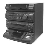
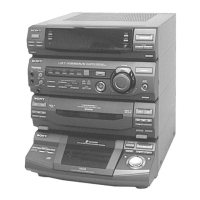
Detailed diagram and list of front panel controls for the main unit.

DISASSEMBLY

Case and Rear Panel

Exploded view and instructions for removing the outer case.

Tape Mechanism Deck Section

Steps for disassembling the tape mechanism deck.

Optical Pick-up, Sled Motor, Spindle Motor

Details the removal of the optical pick-up, sled motor, and spindle motor.

TEST MODE

MC Cold Reset

Clears all data and resets the unit to initial conditions.

CD Delivery Mode

Positions the pickup for safe transport after repair.

MC Hot Reset

Resets the unit while retaining preset data in memory.

Sled Servo Mode

Allows free movement of the CD sled motor for maintenance.

Aging Mode

MECHANICAL ADJUSTMENTS

ELECTRICAL ADJUSTMENTS

Tape Deck Section

Covers tape deck electrical adjustments like azimuth and speed.

Record/Playback Head Azimuth Adjustment

Procedure for adjusting the azimuth of the record/playback heads.

Tape Speed Adjustment (Deck A)

Procedure for adjusting tape speed on Deck A.

Playback Level Adjustment (Deck A)

Procedure for adjusting playback level on Deck A.

Record Bias Current Adjustment (Deck B)

Procedure for adjusting record bias current on Deck B.

Record Level Adjustment (Deck B)

Procedure for adjusting record level on Deck B.

CD SECTION

DIAGRAMS

CD Section Block Diagram

Visual representation of the CD player's signal paths and components.

Tape Deck Section Block Diagram

Visual representation of the tape deck's signal paths and components.

Main Section Block Diagram (1/2)

Visual representation of the main section's signal paths and components.

Main Section Block Diagram (2/2)

Continues the visual representation of the main section's signal paths.

Display/Key Control/Power Supply Section Block Diagram

Block diagram of the display, key control, and power supply circuitry.

EXPLODED VIEWS

Case and Rear Panel Section

Exploded view of the case and rear panel section with part numbers.

Front Panel Section-1

Exploded view of the front panel section 1, detailing parts.

Front Panel Section-2

Exploded view of the front panel section 2, detailing parts.

Chassis Section

Exploded view of the chassis section, including transformer and boards.

Tape Mechanism Deck Section-1

Exploded view of the tape mechanism deck section 1.

Tape Mechanism Deck Section-2

Exploded view of the tape mechanism deck section 2.

Tape Mechanism Deck Section-3

Exploded view of the tape mechanism deck section 3.

CD Mechanism Deck Section

Exploded view of the CD mechanism deck section.

Base Unit Section

Exploded view of the base unit section.

Related product manuals