EasyManua.ls Logo

Sony HDR-CX535 User Manual

Sony HDR-CX535
76 pages
To Next Page IconTo Next Page
Page #1 background imageLoading...
Page #1 background image
SERVICE MANUAL
Revision History
Published by Sony Techno Create Corporation
Sony Corporation
LEVEL 3
HDR-CX530E/CX535/CX610E/PJ530E/PJ540/PJ540E/PJ610E_L3
Check the SERVICE NOTE (LEVEL 2) before the service.
983477311.pdf
Digital HD Video Camera Recorder
The components identified by mark
0 or dotted line with mark 0 are
critical for safety.
Replace only with part number
specified.
Les composants identifiés par une
marque 0 sont critiques pour la
sécurité.
Ne les remplacer que par une
pièce portant le numéro spécifié.
9-834-773-11
Ver. Date History Contents
S.M. Rev.
issued
1.0 2014.01 Official Release
2014A08-1
© 2014.01
MODEL GROUP
Projector Model: PJ530E/PJ540/PJ540E/PJ610E
Non Projector Model: CX530E/CX535/CX610E
Ver. 1.0 2014.01
Photo: HDR-PJ540/BROWN
US Model
Canadian Model
AEP Model
UK Model
North European Model
E Model
Australian Model
Hong Kong Model
Chinese Model
Korea Model
Tourist Model
Japanese Model
HDR-CX530E/CX535/CX610E/PJ530E/
PJ540/PJ540E/PJ610E
Distinguishing MM-102 Boards (HDR-CX610E/PJ610E)
Three types of MM-102 board are used in this unit.
When repairing an MM-102 board, identify its type by the IC model names printed on the surface of IC8101 and IC8201 on the MM-102 board.
IC8101 IC8201
Type A KLMBG4WE4A-A001T01 KLMBG4WE4A-A001T01
Type B THGBM7G8T4JBAIRH10 THGBM7G8T4JBAIRH10
Type C KLMCG8WE4A-A001T01 No Mount
Note:
IC8101 and IC8201 cannot be replaced with any other type of IC. Be sure to replace them with the same type of IC.
When replacing Type A or Type B of IC8101 and IC8201, be sure to replace IC8101 and IC8201 together.
Question and Answer IconNeed help?

Do you have a question about the Sony HDR-CX535 and is the answer not in the manual?

Sony HDR-CX535 Specifications

General IconGeneral
Camera TypeCamcorder
Video Resolution1920 x 1080 (Full HD)
MicrophoneBuilt-in stereo microphone
Microphone Operation ModeStereo
HDMI OutputYes (Micro HDMI)
USB PortYes (USB 2.0)
Aperturef/1.8-F4.0
Image StabilizationOptical SteadyShot
LCD Screen Size3.0"
Recording MediaSD card
Supported Flash MemoryMemory Stick Micro, SD Card
Video FormatAVCHD
SpeakerBuilt-in
Battery TypeInfoLithium NP-FV50
Battery LifeApprox. 2 hours 15 minutes (LCD screen)

Summary

Service Manual Overview

Revision History

Details revisions and updates made to the service manual over time.

MM-102 Board Identification

Provides guidance on identifying different types of MM-102 boards based on IC model names.

Service Safety Procedures

Unleaded Solder and Lead-Free Mark

Information on using unleaded solder and identifying lead-free components on PCBs.

Electrical Parts List

Parts List Conventions

Conventions for parts list notations, safety components, and general part identification.

4. Block Diagrams

Overall Block Diagram (1/4)

First part of the overall block diagram, showing major system components and their connections.

Overall Block Diagram (2/4)

Illustrates interconnections between flexible boards and system modules.

Overall Block Diagram (3/4)

Block diagram section showing control switches, microphones, and other peripheral interfaces.

4-5. Power Block Diagram (1/3)

Power Supply Circuit Overview

Overview of the power block diagrams, showing main power supply circuits and voltage regulation.

Power Management and DC/DC Converters

Details power management ICs and DC/DC converters for voltage regulation and power distribution.

Power Distribution to Specific Boards

Illustrates power distribution to various boards like FP-2193, PD-1031, and PJ-1005.

5. Frame Schematic Diagrams

Frame Schematic (1/2)

First part of the frame schematic, showing the physical arrangement of main components and connectors.

Frame Schematic (2/2)

Diagrams showing connections of flexible boards to other units like the projector and headphone jacks.

6. Schematic Diagrams and Printed Wiring Boards

Schematic Diagram Conventions

Notes on component symbols, units, and notations used in schematic diagrams.

Printed Wiring Board Conventions

Notes on PWB conventions, including solder types, panel designations, and component markings.
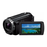
Related product manuals