Do you have a question about the Sony HST-V102 and is the answer not in the manual?
Identifies the location of all controls and indicators on the unit.
Procedures for mechanical adjustments like torque and head azimuth.
Procedures for electrical adjustments in the cassette deck section.
Visual representation of semiconductor component lead configurations.
Block diagrams illustrating the integrated circuits used in the system.
Overall system block diagram showing functional units and connections.
Diagrams showing the layout of printed wiring boards for component placement.
Detailed schematic for the tuner section of the device.
Detailed schematic for the main section of the device.
Exploded view of the cabinet and its associated parts.
Exploded view of the front panel and its components.
Exploded view of the first part of the mechanism deck.
Exploded view of the second part of the mechanism deck.
Exploded view of the third part of the mechanism deck.
Exploded view of the fourth part of the mechanism deck.
Exploded view of the fifth part of the mechanism deck.
Exploded view of the sixth part of the mechanism deck.
Exploded view of the turntable player section.
| Brand | Sony |
|---|---|
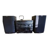
| Model | HST-V102 |
| Category | Stereo System |
| Language | English |