6-74
HVR-V1J/V1U/V1N/V1E/V1P/V1C
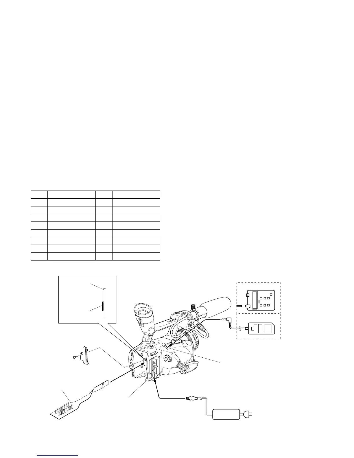
LANC jack
AC IN
DC IN jack
AC adaptor
CPC-7 jig
(J-6082-382-A)
Adjustment remote
commander
(RM-95)
(NEW LANC JIG)
1
16
1
16
CN1014
TT-003 board
1-4. ELECTRONIC VIEWFINDER SYSTEM
ADJUSTMENTS
Before perform the viewfinder system adjustments, check the data
of page: 0, address: 10 is “00”.
If not, select page: 0, address: 10, and set the data “00”.
Note 1: Taken an extreme care not to destroy the liquid crystal
display module by static electricity when replacing it.
Note 2: Perform the following data setting before the viewfinder
system adjustments.
1) Select page: 3, address: C4, and set data: 67.
2) Select page: 3, address: C5, and set data: 01.
Reset the data after completing adjustment.
1) Select page: 3, address: C4, and set data: 00.
2) Select page: 3, address: C5, and set data: 00.
Switch setting
1) REC FORMAT (Menu setting) ............................ HDV 1080i
[Adjusting connector]
Most of the measuring points for adjusting the viewfinder system
are concentrated in CN1014 of the TT-003 board.
Connect the Measuring Instruments via the CPC-7 jig (J-6082-
382-A).
The following table shown the Pin No. and signal name of CN1014.
Pin No.
Signal Name
Pin No.
Signal Name
1 EVF_COM_DC 9 RF_MON
2 REG_GND 10 REG_GND
3 EXT_DA 11 SWP
4 EVF_VCO 12 FRRV
5 EVF_VG 13 REC_CRRT1_S
6 PSIG 14 REC_CRRT0_S
7 REG_GND 15 REC_CRRT1_C
8 REG_GND 16 REC_CRRT0_C
Fig. 6-1-26
 Loading...