6-129
HVR-V1J/V1U/V1N/V1E/V1P/V1C
6-3. VIDEO SECTION ADJUSTMENTS
3-1. PREPARATIONS BEFORE ADJUSTMENTS
3-1-1. Precautions on Adjusting
Note: Before performing the adjustment, check the data of page:
0, address: 10 is “00”. If not, select page: 0, address: 00,
and set data “00”.
1) The adjustments of this unit are performed in the VTR mode
(PLAY/EDIT mode) or camera mode (CAMERA-TAPE
mode).
3-1-2. Adjusting Connectors
The measuring point of the playback RF signal is CN1014 of TT-
003 board. Connect the measuring instruments via the CPC-7 jig
(J-6082-382-A). Refer to “MECHANISM SECTION ADJUST-
MENT” for the measuring method. The following table lists the
pin numbers and signal names of CN1014.
Pin No.
Signal Name
Pin No.
Signal Name
1 EVF_COM_DC 9 RF_MON
2 REG_GND 10 REG_GND
3 EXT_DA 11 SWP
4 EVF_VCO 12 FRRV
5 EVF_VG 13 REC_CRRT1_S
6 PSIG 14 REC_CRRT0_S
7 REG_GND 15 REC_CRRT1_C
8 REG_GND 16 REC_CRRT0_C
Table 6-3-1
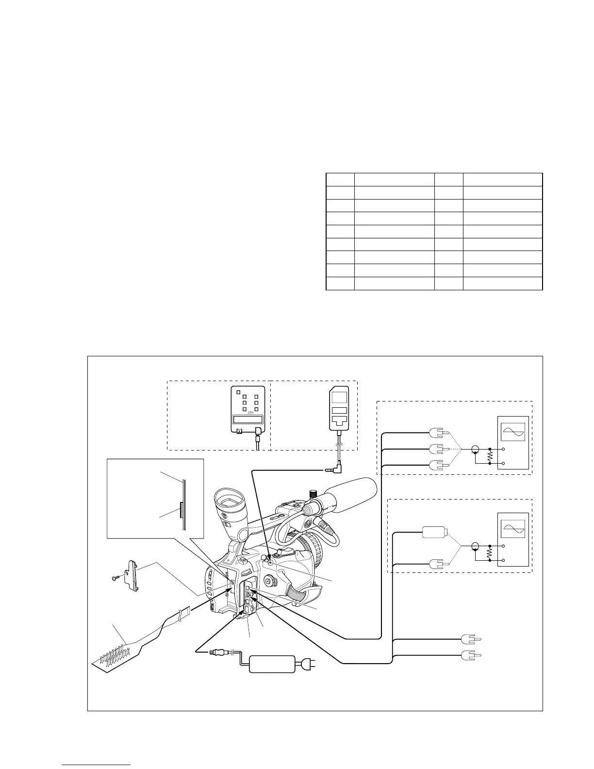
3-1-3. Connecting the Equipment
Connect the measuring instruments as shown in Fig. 6-3-1, and
perform the adjustments.
LANC jack
A/V jack
Audio L (White)
Audio R (Red)
Video
(Yellow)
S Video
(Black)
COMPONENT
OUT jack
Pr (Red)
Pb (Blue)
Y (Green)
AC IN
DC IN jack
VIDEO system adjustment (COMPONENT OUT)
VIDEO system adjustment (S VIDEO, VIDEO)
CPC-7 jig
(J-6082-382-A)
1
16
Terminated
75 Ω
Terminated
75 Ω
1
16
CN1014
TT-003 board
Adjustment remote commander
RM-95
(J-6082-053-B)
NEW LANC JIG
(J-6082-565-A)
LANC cable
(J-6082-442-A)
AC adaptor
AC-L15A
(1-479-283-13)
Osilloscope
Osilloscope
 Loading...