HXR-NX5C/NX5E/NX5J/NX5M/NX5N/NX5P/NX5U
2-13
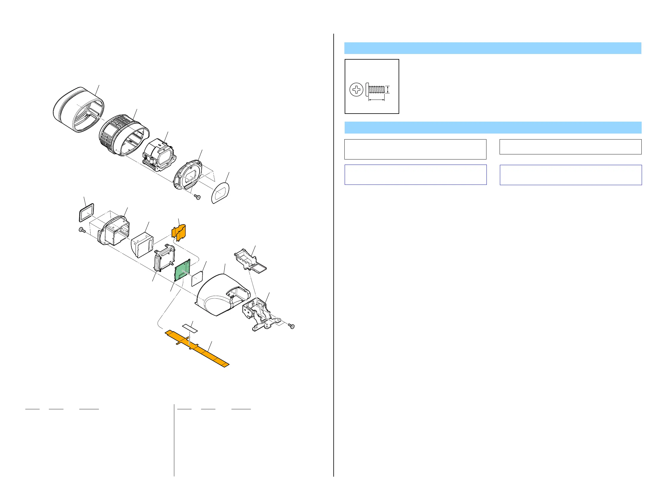
2-1-11. EVF SECTION
Ref. No. Part No. Description Ref. No. Part No. Description
501 4-119-301-01 EYE CUP (SMALL)
502 X-2320-885-1 EYE CUP (93000) ASSY
503 X-2320-861-1 LENS ASSY, VF (Note)
504 4-119-302-01 LID, EYE CUP CABINET
505 4-119-303-01 COVER, EYE CUP CABINET LID
506 3-288-591-01 SHEET, VF PROTECTION
507 3-288-585-01 CASE, PANEL
508 1-873-733-11 FP-776 FLEXIBLE BOARD
509 3-288-586-01 LID, PANEL
510 A-1752-131-A VF-179 BOARD, COMPLETE
* 511 3-299-948-01 SHEET (UU)
512 1-879-859-11 FP-1160 FLEXIBLE BOARD
513 CAUTION TAPE, VF
514 X-2515-771-1 CABINET (94000) ASSY, VF
* 515 4-165-332-01 RETAINER, VF FLEXIBLE
516 X-2515-764-1 TILT ASSY, VF
LCD902 1-802-560-31 LCD MODULE
#53 3-080-206-21 SCREW, TAPPING, P2
Screw
#53
#53
LCD902
#5
501
502
503
504
505
506
507
509
508
510
511
512
515
516
514
513
(16mm × 6.4mm)
(Note)
#53: M2.0 X 5.0 (Tapping)
(Black)
3-080-206-21
5.0
2.0
Note
Caution :
For the part of 513, cut NON WOVEN (T0.25) (3-076-631-01) into
the desired length and use it.
Caution:
Note:
Note: Refer to “Assembly-1: Confirm the Diopter Adjustment
Lever is on the left side when installing the VF Lens Assy”
when installing.
The changed portions from
Ver. 1.0 are shown in blue.
Ver. 1.1 2010.01
 Loading...