Do you have a question about the Sony HXR-NX80 and is the answer not in the manual?
Diagram showing the physical placement of internal circuit boards within the camcorder unit.
Lists the specific tools required for performing maintenance and repairs on the unit.
Important precautions and procedures for replacing internal components and printed wiring boards.
Details regarding fuses and other components critical for circuit protection.
Procedures for connecting and disconnecting flexible flat cables and coaxial cables.
Explanation of the unit's self-diagnosis system and error code display.
Table outlining the function of each internal circuit board in the camcorder.
Detailed table mapping self-diagnosis codes to symptoms and recommended corrections.
Procedures for diagnosing and resolving errors related to the camcorder's shift lens.
Provides specific torque values for various screws used during assembly and disassembly.
Step-by-step instructions for removing and replacing the Cabinet (G) assembly.
Procedure for the removal and replacement of the Heat Sink (GP) assembly.
Detailed steps for removing and installing the GR-1003 circuit board.
Instructions for disassembling and reassembling the Top Cabinet assembly.
Procedure for the removal and installation of the EF-1003 circuit board.
Step-by-step guide for replacing the IR-1009 circuit board.
Procedure for removing and replacing the Inner Mold (T) assembly.
Detailed steps for accessing and replacing components within the Cabinet (R) section.
Instructions for removing and installing the CK-1019 circuit board.
Procedure for the removal and installation of the PD-1054 circuit board.
Step-by-step guide for removing and replacing the display module assembly.
Procedure for installing the FP-2264 flexible board and associated magnet.
Detailed steps for accessing and replacing components within the BT Panel section.
Instructions for removing and installing the ZM-1005 circuit board.
Procedure for removing and replacing the VF (Viewfinder) assembly.
Step-by-step instructions for replacing the MS-1037 circuit board.
Procedure for the removal and installation of the VC-1045 main circuit board.
Detailed steps for accessing and replacing components within the lens assembly.
Procedure for removing and replacing the Z Nut component (1730).
Procedure for replacing the P Frame Moving Assembly component (1730).
Detailed steps for accessing and replacing components within the handle assembly.
Instructions for removing and installing the HS-1003 circuit board.
Procedure for the removal and installation of the HN-1004 circuit board.
Step-by-step guide for replacing the XL-1005 circuit board.
Details required software and steps for performing electrical adjustments.
Description of the CM-1016 CMOS image sensor board and its components.
Description of the interface shoe functionality and related boards.
Description of the manual lens ring input signals and processing.
Description of the WF-1008 wireless LAN antenna board.
Description of various switches, buttons, and sensors on different boards.
Description of terminal blocks for user interface connections.
Description of the LCD panel interface and related components.
Description of the EVF OLED interface and associated boards.
Description of the MS-1037 memory card interface and its components.
Description of the shake detection sensors and their signal paths.
Description of the NFC interface signals and processing.
Description of handle-related boards and audio processing.
Description of the main system components, including the VC-1045 board.
Important notes regarding safety, part standardization, stock, and harnesses.
Detailed exploded diagrams illustrating the assembly of various parts.
List of all accessories supplied with the camcorder unit.
Block diagram showing the overall system connections.
Block diagram detailing connections between boards.
Block diagram showing connections to interface boards.
Block diagram illustrating power and control signal paths.
Block diagram detailing connections for the XLR handle unit.
Block diagram of the main power supply circuits.
Block diagram of power supply converters and regulators.
Block diagram of power supply regulators and voltage outputs.
Block diagram of power supply switches and memory interfaces.
Block diagram of power supply for the handle unit and audio circuits.
Wiring diagram showing internal frame connections.
Wiring diagram showing internal frame connections.
Wiring diagram showing internal frame connections.
| Storage temperature (T-T) | -20 - 60 °C |
|---|---|
| Operating temperature (T-T) | 0 - 40 °C |
| Video resolutions | 1280 x 720, 1440 x 1080, 1920 x 1080, 3840 x 2160 pixels |
| Maximum frame rate | 120 fps |
| Supported video modes | 1080p, 2160p |
| Video formats supported | AVC, AVCHD, H.264, MPEG4 |
| Maximum video resolution | 3840 x 2160 pixels |
| Audio system | Dolby Digital 2.0 |
| PCM digital audio | 16-bit/48 kHz |
| Built-in microphone | Yes |
| Audio formats supported | LPCM |
| Digital zoom | - x |
| Optical zoom | 12 x |
| Focal length range | 9.3 - 111.6 mm |
| Interchangeable lens | - |
| Focal length (35mm film equivalent) | 32.8 - 393.6 mm |
| Camera shutter speed | 1/10000 s |
| Display diagonal | 3.46 \ |
| Display resolution (numeric) | 1560000 pixels |
| Wi-Fi standards | 802.11b, 802.11g, Wi-Fi 4 (802.11n) |
| Sensor type | CMOS |
| Total megapixels | 14.2 MP |
| Optical sensor size | 1 \ |
| PictBridge | No |
| Headphone outputs | 1 |
| Headphone connectivity | 3.5 mm |
| USB 2.0 ports quantity | USB 2.0 ports have a data transmission speed of 480 Mbps, and are backwards compatible with USB 1.1 ports. You can connect all kinds of peripheral devices to them. |
| Memory slots | 2 |
| Camcorder media type | Memory card |
| Compatible memory cards | SD, SDHC, SDXC |
| Internal storage capacity | - GB |
| Battery type | NP-FV70A |
| Battery voltage | 7.4 V |
| Battery capacity | - mAh |
| Battery life (max) | 4.4 h |
| Battery technology | Lithium |
| Focus adjustment | Auto/Manual |
| Closest focusing distance | 0.01 m |
| Viewfinder type | Electronic |
| Viewfinder resolution | 2360000 pixels |
| Viewfinder screen size | 0.39 \ |
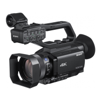
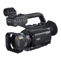
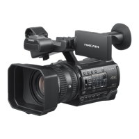
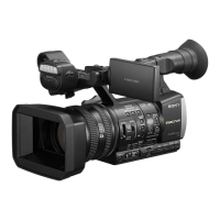
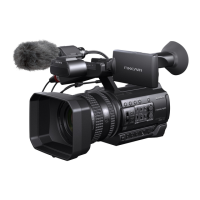
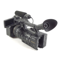
| Camcorder type | Handheld camcorder |
| Minimum illumination | 1.7 lx |
| Product color | Black |
| Cables included | USB |
| Number of batteries included | 1 pc(s) |
| Maximum image resolution | - pixels |
| Depth | 287 mm |
|---|---|
| Width | 130 mm |
| Height | 181.5 mm |
| Weight | 1320 g |