EasyManua.ls Logo

Sony ICF-C240 User Manual

Sony ICF-C240
4 pages
To Next Page IconTo Next Page
Page #1 background imageLoading...
Page #1 background image
SECTION
1
ELECTRICAL
ADJUSTMENTS
FM
Section
AM
Section
oii
SERVICE
MANUAL
AEP
Model
isi
=
[-~}H
Pz)
antenna
close
to
ww
the
set,
3
ICF-C240
TIME
SET-M
button.
ALARM
button
speaker
terminal
[1
semen
TIME
SET-H
button-
SLEEP
button
‘00H,
80%
@
Repeat
the
procedures
in
each
adjustment
CLOCK
button.
REPEAT
ALARM/
AM
modulation
several
times,
and
the
frequency
coverage
and
SPEER
OFF
button
s2askiis
frequency
Output
level
as
tow
as
possbte
tracking
adjustments
should
be
finally
done
by
output
level
:as
low
as
possible
the
trimmer
capacitors,
ALARM
(RADIO/BUZZER)
Ne
Band
(FM/AM)
selector
FM
FREQUENCY
AM_IF
ALIGNMENT
VOL
(volume)
control
COVERAGE
ADJUSTMENT
Adjust
for
a
maximum
reading
TUNING
control
|
‘Adjust
for
a
maximum
reading
on
VTVM.
|
on
VTVM,
12
i
L4
87.35(87.3)MHz
455kHz
{
cT2
108.05(108.3)
MHz
\
AM
FREQUENCY
SPECIFICATIONS
FM
TRACKING
ADJUSTMENT
COVERAGE
ADJUSTMENT
Frequency
range
FM
AM
MAIN
BOARD
REMOVAL
Adjust
for
a
maximum
reading
Adjust
for
a
maximum
reading
AEP
model
|
87.6—107.5MHz
|
531—1,602kHz
o
Turn
TUNING
knob
fully
clockwise.
coy)
on
VTVM
IT
model
|
87.5—108MHz
526.5—1,606.5kHz
e
R
4B
2.6X5
s
LS,
L6
87.35(87.3)MHz
13
520(516.5)kHz
einoveiscrew
(48.26%)
Ct
108.05
(108.3)
MHz
crt
1,650(1,631.5)kHz
Antenna
FM:
AC
power
cord
antenna
©
Release
fook,
(_):IT
model
Seu
ye
Lae
ere
esl
de
©
Remove
main
board
pressing
down
TUNING
knob.
speaker
pprox.
6.6
cm
(27,
inches)
dia.
¢
"
a
i
[AM
TRACKING
ADJUSTMENT]
Power
output
100mW
(at
10%
harmonic
distortion)
Note:
When
installing
main
board,
align
shaft
of
VOL
knob
AM
TRACKING
ADJUSTMENT.
Power
requirement
220V
AC,
50H2
with
a
hole
of
adjustable
resistor.
‘Adjust
for
a
maximum
reading
For
the
power
backup
function:
on
VTVM,
9V
DC,
one
6F
22
battery
Battery
life
Approx.
80
hours,
using
Sony
battery
S-O06P
(U)
°
EL
S20kHz
Dimensions
Approx.
181.5x59x144mm
(w/h/d)
CT3
1,400kHz
(7.x
2%
x54,
inches)
ae
incl.
projecting
ports
and
controls.
Weight
Approx.
520g
(1
Ib
302)
it
incl.
batt
te
.
not
inch
battery
alle
BOAR
[MAIN
BOARD]
-
component
side
-
Design
and
specifications
subject
to
change
without
notice
|
adjustable
i
resistor
FEATURES
*
Electronic
digital
alarm
clock
and
sleep
timer
are
combined.
+
Two
wake-up
modes
available:
radio
or
buzzer
alarm.
*
REPEAT
ALARM
bar,
operable
with
a
feather-light
touch,
offers
two
functions:
snooze
alarm
and
sleep
timer
turn
off.
*
Power
back-up
function
to
keep
the
clock
operating
during
a
power
interruption,
using
an
optional
6F22
battery.
VOL
knob
|
@
TuNING
KNos
|
SAFETY-RELATED
COMPONENT
WARNING!!
|
|
&
COMPONENTS
IDENTIFIED
BY
MARK
/\
OR
DOTTED
@
screw
LINE
WITH
MARK
\
ON
THE
SCHEMATIC
DIAGRAMS
+8
265
AND
IN
THE
PARTS
LIST
ARE
CRITICAL
TO
SAFE
OPERATION.
REPLACE
THESE
COMPONENTS
WITH
SONY
PARTS
WHOSE
PART
NUMBERS
APPEAR
AS
tas
oaeenmemmseen
FM/AM
DIGITAL
CLOCK
RADIO
Question and Answer IconNeed help?

Do you have a question about the Sony ICF-C240 and is the answer not in the manual?

Sony ICF-C240 Specifications

General IconGeneral
TypeClock Radio
Tuner BandsAM/FM
DisplayLED
Snooze FunctionYes
Power Source Voltage120V AC
Power SourceAC
Alarm TypeRadio or Buzzer

Summary

SECTION 1 ELECTRICAL ADJUSTMENTS

FM FREQUENCY COVERAGE ADJUSTMENT

Adjust for a maximum reading on VTVM for FM frequency coverage.

AM IF ALIGNMENT

Adjust for a maximum reading on VTVM for AM intermediate frequency.

FM TRACKING ADJUSTMENT

Adjust for a maximum reading on VTVM for FM tracking.

AM FREQUENCY COVERAGE ADJUSTMENT

Adjust for a maximum reading on VTVM for AM frequency coverage.

AM TRACKING ADJUSTMENT

Adjust for a maximum reading on VTVM for AM tracking.

MAIN BOARD REMOVAL

SECTION 2 DIAGRAMS

2-1. PRINTED WIRING BOARDS

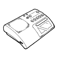
Diagrams showing the physical layout of components on the printed circuit boards.

IC Block Diagram

Functional block diagram illustrating the integrated circuits and their connections.

Semiconductor Location

Identifies the specific locations of semiconductor components on the circuit board.

2-2. SCHEMATIC DIAGRAM

Semiconductor Lead Layouts

Illustrates the lead pin configurations for various semiconductor components.

SECTION 3 EXPLODED VIEW

SECTION 4 ELECTRICAL PARTS LIST

CAPACITORS

List of capacitors with part numbers, values, and specifications.

RESISTORS

List of resistors with part numbers, values, and specifications.

TRANSFORMER, POWER

Details for the power transformer component.

ACCESSORY & PACKING MATERIAL

List of accessories and packing materials included with the unit.
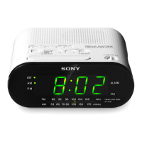
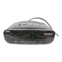
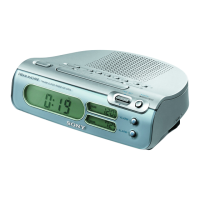
Related product manuals