Do you have a question about the Sony ICF-C290 and is the answer not in the manual?
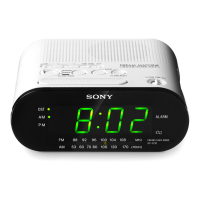
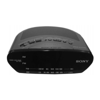
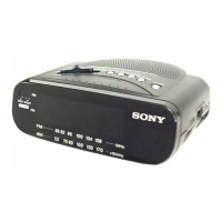
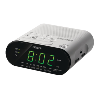
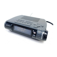
Details on time display formats and radio frequency ranges for different models.
Information on speaker, power output, and electrical requirements.
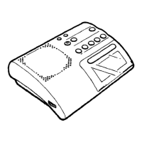
Provides the physical dimensions and mass of the device.
Instructions for replacing ceramic filters, emphasizing matching specifications.
Guidelines for handling chip components, especially tantalum capacitors.
Highlights critical components for safe operation and replacement requirements.
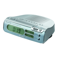
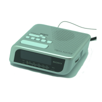
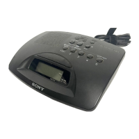
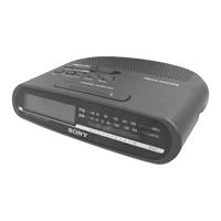
Overview of device features, battery backup, and installation.
Instructions for setting the clock and using the radio functions.
Guides on setting the alarm and sleep timer, including combined use.
Procedure for setting the power cord and installing the lower cabinet.
Instructions for adjusting various knobs and shafts with directional indicators.
Procedures for FM frequency coverage and tracking adjustments.
Guides for AM/LW frequency coverage, tracking, and IF adjustments.
Visual representation of component placement on the main printed wiring board.
Detailed electrical schematic for the main board, excluding the E model.
Component layout for the main board and power supply board of the E model.
Detailed electrical schematic for the main board of the E model.
Functional block diagrams for IC1 (CXA1019S) and IC2 (LM8560N).
Visual breakdown of the device with a comprehensive list of parts.
Listings for various capacitors, ceramic filters, and crystal filters.
Details on connectors, trimmers, and miscellaneous electrical parts.
Listings for variable capacitors, diodes, integrated circuits, coils, transistors, and resistors.
Details on switches, transformers, miscellaneous items, and accessories.
Details the addition of CET (East European, Russia) and Argentina models.
Highlights differences in parts and manuals for new models.
| Type | Clock Radio |
|---|---|
| Brand | Sony |
| Model | ICF-C290 |
| Power Source | AC Power |
| Tuner Bands | AM/FM |
| Display Type | LED |
| Snooze Function | Yes |
| Battery Backup | Yes |
| Alarm Type | Buzzer, Radio |
| Weight | 1.1 lbs |