EasyManua.ls Logo

Sony ICF-C212 User Manual

Sony ICF-C212
16 pages
To Next Page IconTo Next Page
Page #1 background imageLoading...
Page #1 background image
ICF-C212
SERVICE MANUAL
FM/AM CLOCK RADIO
SPECIFICATIONS
E Model
Australian Model
Ver 1.0 2003.03
9-877-143-01
2003C0200-1
© 2003.03
Sony Corporation
Personal Audio Company
Published by Sony Engineering Corporation
Time display:
North and South America, Australia:12-hour system
Other countries/regions: 24-hour system
Frequency range:
FM 87,5 - 108 MHz
AM 530 - 1 710 kHz
Speaker:
Approx. 6.6 cm (2
5
8
inches) dia., 8
Power output:
150 mW (at 10 % harmonic distortion)
Power requirements:
230 V AC, 50 Hz
For the power back-up function: 9 V DC, one 6F22 battery
Battery life:
Approx. 80 hours, using Sony 006P (6F22) battery
Dimensions:
Approx. 165 x 64.5 x 146 mm
(w/h/d) (6
1
2
x 2
5
8
x 5
3
4
inches) incl.
projecting parts and controls
Mass:
Approx. 522 g (1 lb 3 oz.) not incl. battery
Design and specifications are subject to change without notice.
Question and Answer IconNeed help?

Do you have a question about the Sony ICF-C212 and is the answer not in the manual?

Sony ICF-C212 Specifications

General IconGeneral
Display typeLED
Radio typeClock
Tuner typeAnalog

Summary

Device Specifications Overview

Time Display and Frequency Range

Covers time display systems and radio frequency ranges.

Power, Audio, and Battery Specs

Details power requirements, output, speaker, and battery life.

Physical Dimensions and Mass

Lists device dimensions and weight.

SECTION 1 GENERAL

Controls and Functions Overview

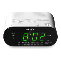
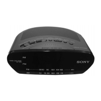
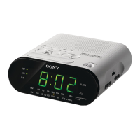
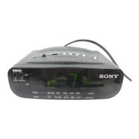
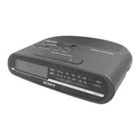
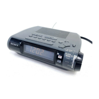
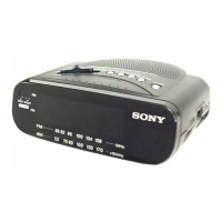
Details the location and purpose of all device controls and indicators.

Core Device Operations

Summarizes key functions like setting time, alarm, and operating radio.

SECTION 2 DISASSEMBLY

Cabinet Disassembly (Upper)

Step-by-step guide for removing the upper cabinet.

Main Board Disassembly

Instructions for accessing and removing the main circuit board.

Power Cord Installation

Procedure for routing and securing the power cord.

Pointer Installation

Steps to correctly install the tuning pointer.

SECTION 3 ELECTRICAL ADJUSTMENTS

AM Band Adjustments

Covers IF, frequency coverage, and tracking for AM radio.

FM Band Adjustments

Covers IF, frequency coverage, and tracking for FM radio.

SECTION 4 DIAGRAMS

Printed Wiring Boards

Visual representation of component layout on the main board.

Schematic Diagram

Detailed electrical schematic of the device circuitry.

IC Block Diagrams

Block diagrams illustrating the internal functions of key integrated circuits.

SECTION 5 EXPLODED VIEW

Exploded View Diagram

Illustrated breakdown of the device showing component relationships.

SECTION 6 ELECTRICAL PARTS LIST

Passive Components

Lists capacitors, resistors, coils, filters, and trimmers.

Active Components

Details diodes, transistors, and integrated circuits.

Other Electrical Parts

Includes switches, transformers, variable resistors, and cables.

Miscellaneous and Accessories

Lists miscellaneous items and device accessories.

REVISION HISTORY

Related product manuals