ICF-C212
7
SECTION 3
ELECTRICAL ADJUSTMENTS
TUNER SECTION
AM/LW Section
Procedure :
BAND : AM
VOLUME : MIN
FM Section
Procedure :
BAND : FM
VOLUME : MIN
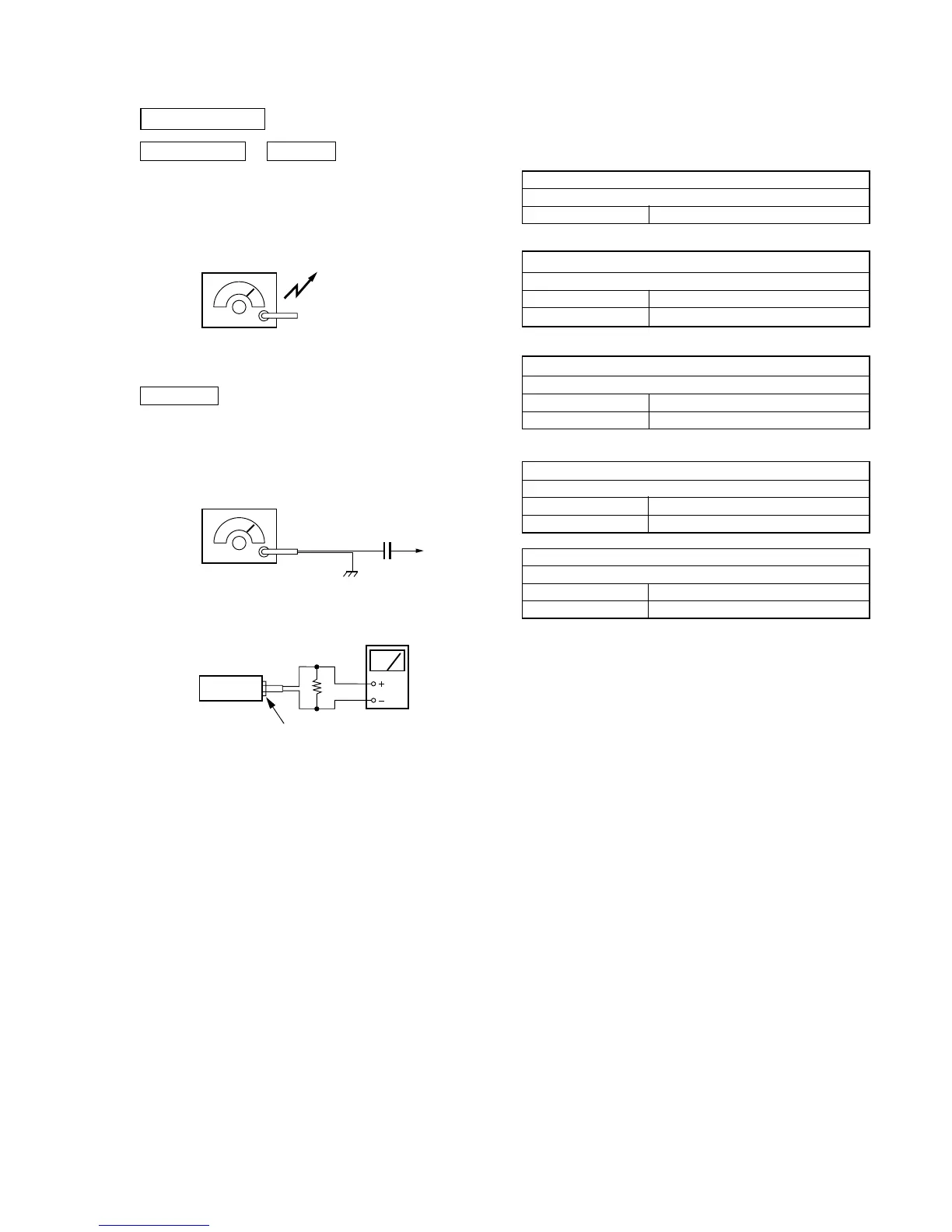
AM RF signal
generator
30% amplitude modulation by 400Hz
signal.
Output level : as low as possible
Put the lead-wire
antenna close to
the set.
FM RF signal
generator
22.5kHz frequency deviation by
400Hz signal.
Output level : as low as possible
antenna
terminal
(JW1)
0.01µF
set
8
Ω
speaker terminal
level mete
• Repeat the procedures in each adjustment several times, and the
frequency coverage and tracking adjustments should be finally
done by the trimmer capacitors.
AM IF ADJUSTMENT
Adjust for a maximum reading on level meter.
T1 455kHz
AM FREQUENCY COVERAGE ADJUSTMENT
Adjust for a maximum reading on level meter.
L4 520kHz <516.5kHz>
CT4 1,750kHz <1631.5kHz>
AM TRACKING ADJUSTMENT
Adjust for a maximum reading on level meter.
L1 620kHz
CT1 1,400kHz
FM FREQUENCY COVERAGE ADJUSTMENT
Adjust for a maximum reading on level meter.
L3 86.5MHz <87.35MHz>
CT3 109.5MHz <108.25MHz>
FM TRACKING ADJUSTMENT
Adjust for a maximum reading on level meter.
L2 86.5MHz <87.35MHz>
CT2 109.5MHz <108.25MHz>
0dB=1µV