ILCE-7SM2_L2
2-3
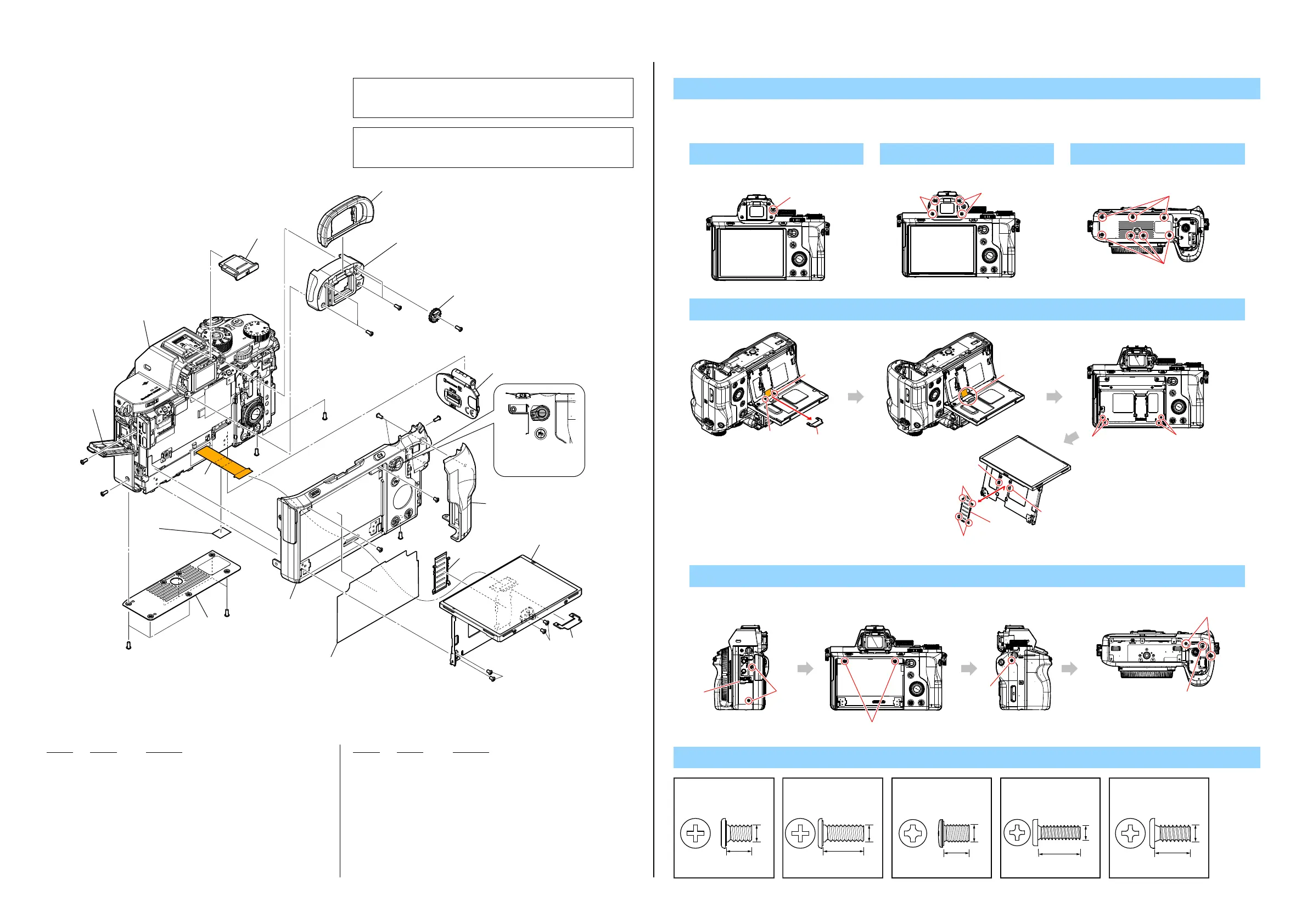
2-1. EXPLODED VIEWS
2-1-1. REAR SECTION-1
Ref. No. Part No. Description
Ref. No. Part No. Description
DISASSEMBLY
1. Remove in numerical order (1 to 7) in the left figure.
#290
Back View
2 #290 X 1
1 4-438-734-02 SHOE CAP (875)
2 X-2591-931-2 EYE CUP ASSY (795)
3 X-2591-930-1 COVER ASSY (795), FINDER
* 4 4-154-680-01 CV DIOPTER ADJUST DIAL (857)
5 X-2590-709-1 LID ASSY (786), BT
6 X-2591-928-2 COVER ASSY (795), REAR
7 4-559-162-01 CAP (LC) (786), FLEXIBLE
8 X-2591-272-2 LC FPC CAP T ASSY (786)
9 4-559-275-01 CABINET (786), BM
10 CAUTION SHEET, LC FLEXIBLE FIXED
11 X-2591-929-1 GRIP ASSY (795), REAR
12 4-578-529-01 SHEET (796), FRAME
#1 2-635-562-11 SCREW (M1.7)
#2 2-635-562-31 SCREW (M1.7)
#247 4-412-769-11 SCREW (M1.4), NEW TRU-STAR, P2
#290 4-300-106-11 BTITE (1.4 (CH))
#308 4-300-115-01 TAPPING (1.7) (CH)
When installing,
adjust this position.
#290
#2
#2
#2
#2
#2
#308
#2
#2
#2
#2
#1
#247
#247
#1
#2
1
2
3
4
5
6
7
Rear Section-2
(See page 2-4)
LCD Section
(See page 2-11)
1
2
3
4
5
6
9
10
(Size 7 x 5 mm)
8
7
11
12
6-3
6
7
-2
6-1
#2
#2
Back View
3 #2 X 4
6 LC FPC Cap T ASSY (6-1) → Flexible Board (6-2) → #247 X 4 → Flexible Cap (6-3)
Boss
Boss
-1
-2
#247#247
Back View
Claws
Claws
Boss
Boss
-3
Screw
#2
#2
Bottom View
5 #2 X 7
7 Open the Jack Lid (7) → #2 X 2 → #1 X 2 → #2 X 1 → #2 X 3
#2
Left View
#1
Back View
#2
Right View
Bottom View
#2
#2
#1: M1.7 X 2.5
(Black)
2-635-562-11
2.5
1.7
#2: M1.7 X 4.0
(Black)
2-635-562-31
4.0
1.7
(Black)
4-412-769-11
2.5
1.4
#247: M1.4 X 2.5
#290: M1.4 X 5.0 (Tapping)
(Black)
4-300-106-11
5.0
1.4
#308: M1.7 X 3.5 (Tapping)
(Black)
4-300-115-01
3.5
1.7
CAUTION
For the part of 10: LC Flexible Fixed Sheet, cut the Adhesive Sheet
(4-441-672-01) into the desired length and use it.
注意
10:LCFlexibleFixedSheetは,AdhesiveSheet(4-441-672-01)を切っ
て使用すること。
 Loading...