9
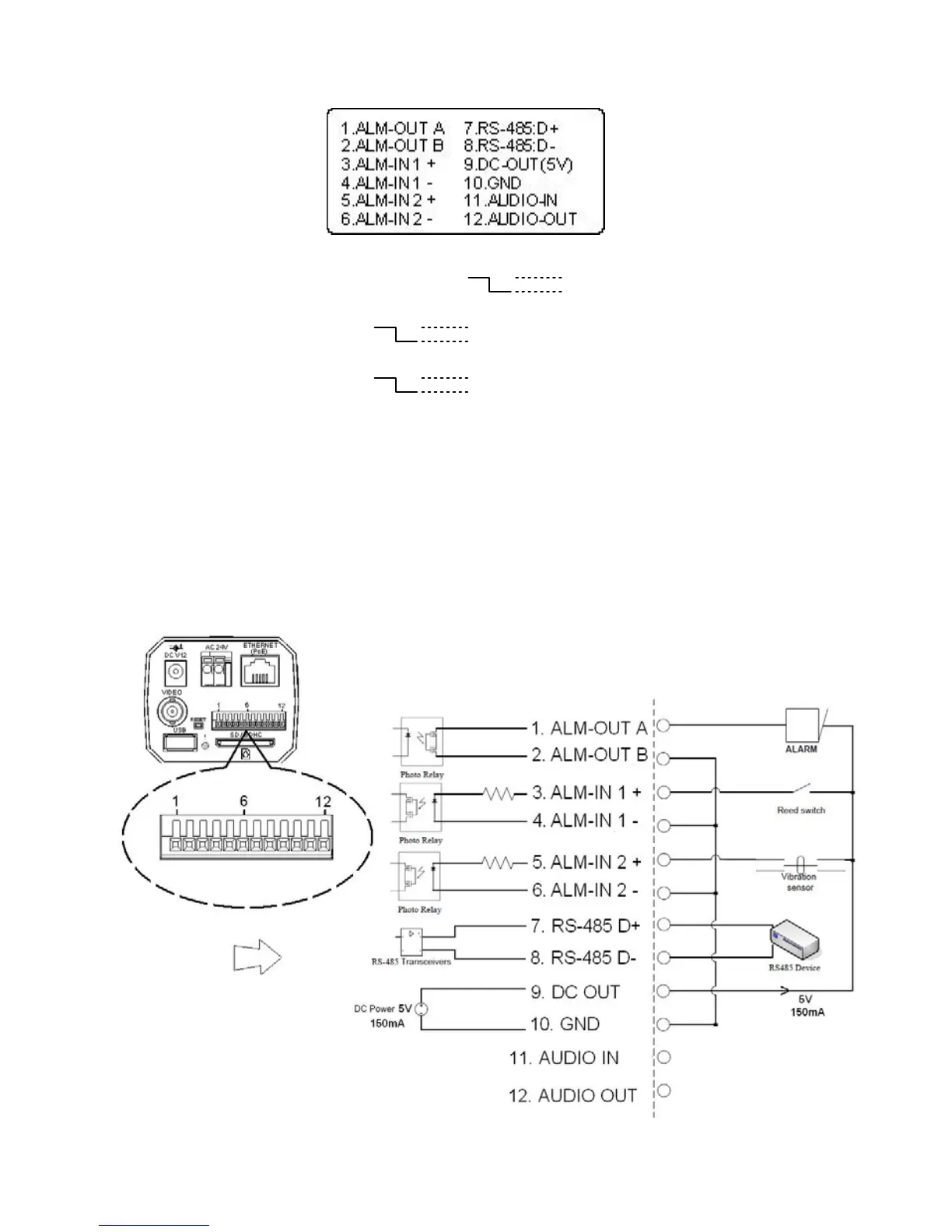
2.2 ALARM I/O
1 & 2. ALARM OUT (OUTPUT): This is an alarm output trigger. Connect this to external
devices such as buzzers or lights. ( )
3 & 4. ALARM IN 1 (INPUT): This is an alarm input that can be programmed in the menu
system to active low. ( )
5 & 6. ALARM IN 2 (INPUT): This is an alarm input that can be programmed in the menu
system to active low. ( )
7. RS-485 D+
8. RS-485 D-
9. DC OUT (5V)
10. GND: Ground contact.
11. AUDIO IN
12. AUDIO OUT: This provides the unit’s audio signal to a speaker.
Alarm wiring diagram:
5V, 20mA
0V(Active)
5V, 20mA
0V(Active)
5V, 20mA
0V(Active)