COLOR REAR VIDEO PROJECTION
SERVICE MANUAL
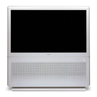
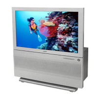
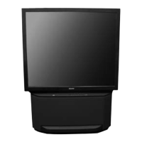
RA-6A
CHASSIS
MODEL NAME REMOTE COMMANDER DESTINATION CHASSIS NO.
9-965-946-07
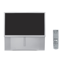
KP-46WT510
RM-Y909 US/CND SCC-M10DA
HISTORY INFORMATION FOR THE FOLLOWING MANUAL:
ORIGINAL MANUAL ISSUE DATE: 6/2003
: UPDATED ITEM
REVISION DATE SUBJECT
6/2003 No revisions or updates are applicable at this time.
6/30/2003 Updated G (Pg. 58) and D (Pg. 77) Schematics,
Added critical symbol to G Board on Exploded View section 6-3. Chassis (Pg. 90)
Updated critical components on Parts Lists (Pgs. 92-135)
8/25/2003 Updated Table of Contents (Pg. 3)
Corrected Diagrams for H2, H1, and H4 Board Removal (Pg. 11)
Replaced 2-11. Service Data Lists with 2-11. Adjustable Service Data Lists
(Replace Pgs. 19-37 with Pgs. 19-29)
Corrected procedures for 2-12. Registration Adjustment (Replace Pg. 38 with Pg. 30)
Corrected procedures for 2-13-2. Copying All Registration Data to Other Modes and
2-14. Auto Registration Offsets (Replace Pg. 42 with Pg. 34)
Corrected Error Codes 54 & 55, 2-15. Auto Registration Error Codes (Replace Pg. 43 with Pg. 35)
Added 2-16. Auto Registration Diagnostics (Replace Pg. 44 with Pg. 36)
Corrected 3-D-Comb # from 5-3. Block Diagram (Replace Pg. 51 with Pg. 43)
Deleted IC308 Block Diagram from 5-5. IC Block Diagrams (Replace Pg. 84 with Pg. 76)
Corrected semiconductors 5-6. Semiconductors (Replace Pg. 88 with Pg. 80)
Corrected Grille piece on cover exploded view diagrams (Replace Pg. 89 with Pg. 81)
11/11/2003 Replaced data relating to CR, CG and CB Boards.
Affects Pages 46-48 (Schematics), 83 (Exploded View), 84-87 (Parts List).
11/16/2004 Removed Note from section 2-12-1. Setup For Adjustment. Note is intended for use by the factory during
production, and should not be performed by service technicians.(Pg. 30)
Updated A Board, Complete PN, Added A Board, Mounted PN,
Added New CRT’s, D Board, introduced new S/N range. Affects S/N’s 8,000,001 to 8,700,000
(Pg. 82 & 83)
11/17/2004 Added new D Board PN to Electircal Parts List Affects S/N’s 8,000,001 to 8,700,000
(Pg. 120 & 124)
8/19/2005 Updated serial number range for D Boards and CRTs (Pg. 82, 83, and 120)
☛