Do you have a question about the Sony KV-21FV1D and is the answer not in the manual?
Details on TV system, color system, channel coverage, and picture tube.
Information on VCR format, recording systems, tape speeds, and recording times.
Covers terminals, power requirements, sound output, dimensions, weight, and accessories.
Explains the self-diagnostic function and initial error indicators.
Details on interpreting the STANDBY lamp flash counts for diagnostics.
How to view diagnostic results and error codes on the screen.
Procedures for clearing diagnostic results and quitting the diagnostic screen.
Schematic illustration of the self-diagnostic circuit components.
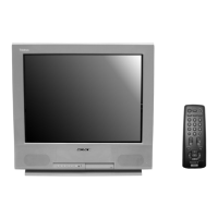
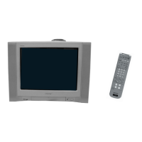
Overview of buttons on the TV set and the remote control.
Instructions for connecting external devices and the aerial.
Guide to navigating menus and performing basic TV functions.
Channel tuning, picture settings, timers, and parental lock operations.
Steps for removing the rear cover and chassis assembly.
Procedures for removing the A board and identifying harness locations.
Detailed instructions for safely removing the picture tube and anode cap.
Steps for preparing the TV and adjusting beam landing.
Procedures for horizontal, vertical, and dynamic convergence.
Instructions for adjusting focus and screen grid (G2) voltage.
Methods for adjusting white balance and correcting picture distortion.
How to enter service mode, read/write memory, and release mode.
Adjusting picture settings and writing standard values to memory.
Overview of using the remote commander for service adjustments.
Table listing service data parameters and their standard values.
Specific adjustments for the A board, including sub-colour.
Schematic block diagrams of the TV and CVM boards.
Diagrams showing the physical location of H10, CVM, and MA10 boards.
Details on PWB layouts and schematic diagram references.
List of semiconductors used, with package and marking information.
Diagram showing parts related to the picture tube assembly.
Exploded view of the main chassis and related components.
Exploded views of the VCR mechanism deck assemblies (1, 2, 3).
List of electrical components for the TV block.
List of electrical components for the CVM block.
List of electrical components for the MA10 block.