EasyManua.ls Logo

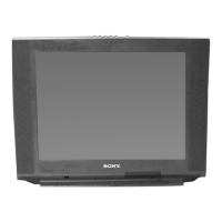
Sony KV-27FS210 User Manual

Sony KV-27FS210
212 pages
To Next Page IconTo Next Page
Page #1 background imageLoading...
Page #1 background image
TRINITRON
®
COLOR TELEVISION
SERVICE MANUAL
BA-5D
CHASSIS
MODEL NAME REMOTE COMMANDER DESTINATION CHASSIS NO.
9-965-941-01
KV-27FS210
RM-Y181 US SCC-S65LA
KV-27FS210
RM-Y181 CANADA SCC-S64HA
KV-29FA210
RM-Y180 LATIN NORTH SCC-S62SA
KV-29FA210
RM-Y180 LATIN SOUTH SCC-S62TA
KV-32FS210
RM-Y181 US SCC-S65NA
KV-32FS210
RM-Y181 CANADA SCC-S64KA
KV-36FS210
RM-Y181 US SCC-S65PA
KV-36FS210
RM-Y181 HAWAII SCC-S67DA
HISTORY INFORMATION FOR THE FOLLOWING MANUAL:
ORIGINAL MANUAL ISSUE DATE: 5/2003
ALL REVISIONS AND UPDATES TO THE ORIGINAL MANUAL ARE APPENDED TO THE END OF THE PDF FILE.
REVISION DATE REVISION TYPE SUBJECT
5/2003 No revisions or updates are applicable at this time.

Table of Contents

Question and Answer IconNeed help?

Do you have a question about the Sony KV-27FS210 and is the answer not in the manual?

Sony KV-27FS210 Specifications

General IconGeneral
BrandSony
ModelKV-27FS210
CategoryTV
LanguageEnglish

Summary

SECTION 1: DISASSEMBLY

1-1. REAR COVER REMOVAL

Procedure for removing the rear cover of the TV chassis.

1-4. PICTURE TUBE REMOVAL

Steps for safely removing the picture tube from the chassis.

SECTION 2: SET-UP ADJUSTMENTS

2-1. BEAM LANDING

Adjusting the convergence of electron beams for optimal picture alignment.

2-5. WHITE BALANCE ADJUSTMENTS

Fine-tuning color balance for accurate picture reproduction.

SECTION 3: SAFETY RELATED ADJUSTMENTS

3-1. HV HOLD-DOWN CONFIRMATION AND READJUSTMENTS

Verifying and adjusting high voltage hold-down for safety.

SECTION 4: CIRCUIT ADJUSTMENTS

4-1. SETTING THE SERVICE ADJUSTMENT MODE

How to enter the TV's service adjustment mode using the remote.

4-4. SERVICE DATA LISTS

Table of default settings and parameters for various service adjustments.

SECTION 5: DIAGRAMS

5-3. BLOCK DIAGRAM

A high-level overview of the TV's internal signal flow and major components.

SECTION 6: EXPLODED VIEWS

6-1. CHASSIS (KV-27FS210 ONLY)

Exploded view showing chassis components and their assembly order for a specific model.

6-2. PICTURE TUBE (KV-27FS210 ONLY)

Exploded view detailing picture tube assembly and related parts.

SECTION 7: ELECTRICAL PARTS LIST

CAPACITOR

List of all capacitors with part numbers, values, and specifications.
Related product manuals