EasyManua.ls Logo

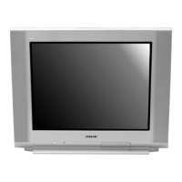
Sony KV-27FS320 User Manual

Sony KV-27FS320
133 pages
To Next Page IconTo Next Page
Page #1 background imageLoading...
Page #1 background image
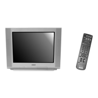
TRINITRON
®
COLOR TELEVISION
SERVICE MANUAL
BA-6
CHASSIS
MODEL NAME REMOTE COMMANDER DESTINATION CHASSIS NO.
9-965-964-03
KV-27FS320
RM-Y196 US SCC-S61S-A
KV-27FS320
RM-Y196 CANADA SCC-S59N-A
KV-32FS120
RM-Y195 US SCC-S61P-A
KV-32FS120
RM-Y195 CANADA SCC-S59K-A
KV-32FS320
RM-Y196 US SCC-S61T-A
KV-32FS320
RM-Y196 CANADA SCC-S59P-A
KV-34FS120
RM-Y195 LATIN NORTH SCC-S73F-A
KV-34FS120
RM-Y195 LATIN SOUTH SCC-S73G-A
KV-36FS120
RM-Y195 US SCC-S61Q-A
KV-36FS120
RM-Y195 CANADA SCC-S59L-A
KV-36FS120
RM-Y195 HAWAII SCC-S74A-A
KV-36FS320
RM-Y196 US SCC-S61R-A
KV-36FS320
RM-Y196 CANADA SCC-S59M-A
KV-36FS320
RM-Y196 HAWAII SCC-S74B-A
KV-38FS120
RM-Y195 LATIN NORTH SCC-S73G-A
HISTORY INFORMATION FOR THE FOLLOWING MANUAL:
ORIGINAL MANUAL ISSUE DATE: 5/2004
:UPDATED ITEM
REVISION DATE SUBJECT
5/2004 No revisions or updates are applicable at this time.
8/2004 Reissue entire manual, Added Wire Dressing for KV-27FS320/32FS320/36FS320
Added Service Data for KV-27FS320/36FS120/38FS120
1/2005 Corrected PN for FBT Assy for KV-32FS320/36FS320 Models (Replace Pg. 105 with Pg. 105)

Table of Contents

Question and Answer IconNeed help?

Do you have a question about the Sony KV-27FS320 and is the answer not in the manual?

Sony KV-27FS320 Specifications

General IconGeneral
BrandSony
ModelKV-27FS320
CategoryTV
LanguageEnglish

Summary

History Information

Specifications

Safety Information

Warnings and Cautions

Presents essential safety notices regarding high voltage and critical components.

Safety Check-Out

Outlines essential checks to perform before releasing the serviced unit to the customer.

Self-Diagnostic Function

Diagnostic Test Indicators

Defines the meaning of different LED flash counts for troubleshooting error conditions.

Self-Diagnostic Screen Display

Details how to access and interpret the self-diagnostic results shown on the screen.

Section 1: Disassembly

1-1. Rear Cover Removal

Details the procedure for removing the rear cover of the television.

1-2. Chassis Assembly Removal

Explains how to remove the main chassis assembly from the TV.

1-3. Service Position

Illustrates the correct service position for accessing internal components.

1-4. Picture Tube Removal

Provides procedures and warnings for safely removing the CRT picture tube.

Cable Wire Dressing

Section 2: Set-Up Adjustments

2-1. Beam Landing

Details the procedure for adjusting the beam landing for optimal picture alignment.

2-2. Convergence

Explains static and dynamic convergence adjustments for color alignment.

2-3. Focus

Describes the procedure for adjusting the picture focus control.

2-6. White Balance Adjustments

Guides on adjusting white balance for accurate color reproduction.

Section 3: Safety Related Adjustments

3-1. HV Hold-Down Confirmation and Readjustments

Details confirmation and readjustment for HV hold-down safety feature.

3-2. B+ Voltage Confirmation and Adjustment

Explains how to confirm and adjust the B+ voltage levels.

Section 4: Circuit Adjustments

4-1. Setting the Service Adjustment Mode

Details the steps to enter and operate the TV's service adjustment mode.

4-4. Service Data Lists

Lists initial service data parameters for various models and adjustments.

4-5. ID Map Table

Presents an ID map table correlating models and destinations with specific IDs.

4-6. A Board Adjustments

Details specific adjustments related to the A Board for picture performance.

Section 5: Diagrams

5-1. Circuit Boards Location

Illustrates the physical location of various circuit boards within the TV chassis.

5-3. Block Diagram and Schematics

Presents block diagrams and detailed schematic diagrams of the TV's circuitry.

A Board Schematic Diagram (1 of 2)

Provides the first part of the A Board schematic diagram.

HM Board Schematic Diagram (1 of 4)

Presents the first part of the HM Board schematic diagram.

5-4. Semiconductors

Section 6: Exploded Views

6-1. Chassis (KV-27FS320/32FS320/36FS320 ONLY)

Shows the exploded view of the chassis assembly for specific models.

6-2. Picture Tube (KV-27FS320/32FS320/36FS320 ONLY)

Illustrates the exploded view of the picture tube assembly for specific models.
6-3. Chassis (KV-32FS120/34FS120/36FS120/38FS120 ONLY)

Shows the exploded view of the chassis assembly for specific models.

6-4. Picture Tube (KV-32FS120/34FS120/36FS120/38FS120 ONLY)

Illustrates the exploded view of the picture tube assembly for specific models.
Section 7: Electrical Parts List

Related product manuals