EasyManua.ls Logo

Sony KV-BT212M40 User Manual

Sony KV-BT212M40
81 pages
To Next Page IconTo Next Page
Page #1 background imageLoading...
Page #1 background image
TRINITRON
®
COLOR TV
CHASSIS
SERVICE MANUAL
BX1S
MODEL COMMANDER DEST. CHASSIS NO.
KV-BT212M40
RM-W101 E SCC-U98S-A
KV-BT212M50
RM-W101 Vietnam SCC-V07P-A
KV-BT212M50
RM-W101 GE SCC-V04M-A
KV-BT212M70
RM-W101 Russia SCC-V13B-A
KV-BT212M80
RM-W101
Saudi Arabia
SCC-V10S-A
KV-BT212M80
RM-W101 Russia SCC-V13C-A
KV-BT212M90
RM-W101
Hong Kong
SCC-U97L-A
KV-BT212N80
RM-W150 Taiwan SCC-V05K-A
MODEL COMMANDER DEST. CHASSIS NO.
RM-W101 RM-W150

Table of Contents

Question and Answer IconNeed help?

Do you have a question about the Sony KV-BT212M40 and is the answer not in the manual?

Sony KV-BT212M40 Specifications

General IconGeneral
BrandSony
ModelKV-BT212M40
CategoryTV
LanguageEnglish

Summary

Disassembly Procedures

Set-Up Adjustments

Beam Landing Adjustment

Adjusting the electron beam landing for optimal picture alignment.

Color Convergence Adjustment

Correcting color convergence for a sharp, unified image.

G2 (Screen) Adjustments

Adjusting the G2/screen voltage for proper brightness.

White Balance Adjustment

Calibrating color temperature and balance.

Circuit Adjustments

Adjustments with Commander

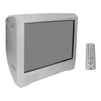
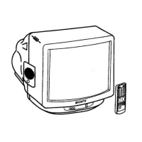
Performing adjustments using the remote commander.

Adjustment Method

General procedure for making circuit adjustments.

Picture Quality Adjustments

Fine-tuning parameters affecting picture output.

Diagrams and Schematics

A Board - Processor Schematic (Block 001)

Detailed schematic diagram for the A board's processor section.

A Board - Power Supply Schematic (Block 003)

Schematic for A board, Power Supply section.

A Board - Deflection Schematic (Block 004)

Schematic for A board, Deflection section.

Self-Diagnostic Functionality

Diagnostic Test Indicators

Explains error codes indicated by the standby light flashes.

Related product manuals