EasyManua.ls Logo

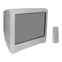
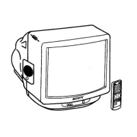
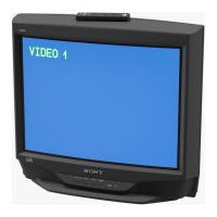
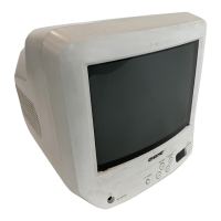
Sony Trinitron KV-BT21M80 User Manual

Sony Trinitron KV-BT21M80
80 pages
To Next Page IconTo Next Page
Page #1 background imageLoading...
Page #1 background image
REVISION HISTORY
BX1
MODEL
KV-BT21M80
PART NO. : 9-872-418-01
NO. SUFFIX DATE SUPPL. / CORR DESCRIPTION
CHASSIS
1 -01 2003/11 -- 1st. Issue

Table of Contents

Questions and Answers:

Sony Trinitron KV-BT21M80 Specifications

General IconGeneral
Screen Size21 inches
Display TechnologyCRT
BrandSony
ModelKV-BT21M80
Aspect Ratio4:3
InputsComposite, RF
Power Consumption90W

Summary

Self Diagnostic Function

Diagnostic Test Indicators

Details error codes indicated by the standby light flashes.

Display of Standby Indicator

Explains the meaning of standby indicator flash counts.

Self-Diagnostic Screen Display

Describes how to view error history on screen.

Handling of Self-Diagnostic Screen Display

Covers clearing and managing diagnostic results.

Section 1 Disassembly

Rear Cover Removal

Step-by-step guide to remove the rear cover.

Speaker Removal

Instructions for safely removing the speaker unit.

Chassis Assy Removal

Steps to remove the main chassis assembly.

Picture Tube Removal

Procedure for safely removing the picture tube.

Section 2 Set-Up Adjustments

Beam Landing

Adjusts the convergence of electron beams for a clear picture.

Convergence

Aligns red, green, and blue electron beams for precise color.

Focus Adjustment

Optimizes picture sharpness by adjusting focus controls.

White Balance Adjustment

Calibrates color reproduction for accurate white balance.

Section 3 Circuit Adjustments

Adjustments with Commander

Explains how to use the remote for service adjustments.

Adjustment Method

Details the general procedure for making adjustments via service mode.

Picture Quality Adjustments

Covers adjustments for PMAX, Contrast, Sub Hue, and Sub Color.

Deflection Adjustment

Instructions for H-Trapezoid adjustment and Normal Mode (50Hz).

Drive Adjustment

Steps for adjusting drive signals for optimal picture output.

Picture Distortion Adjustment

Corrects various picture distortions like centering and sizing.

Section 4 Diagrams

Block Diagram

High-level overview of the TV's internal functional blocks.

Circuit Boards Location

Identifies the physical location of main circuit boards.

Schematic Diagram

Provides detailed circuit schematics for troubleshooting.

C Board Schematic Diagram

Detailed schematic for the C Board (Video Amp).

A Board - Processor (Block A)

Schematic for the A Board Processor section.

A Board - Audio (Block B)

Schematic for the A Board Audio section.

A Board - Power Supply (Block C)

Schematic for the A Board Power Supply section.

A Board - Deflection (Block D)

Schematic for the A Board Deflection section.

A Board - Tuner (Block E)

Schematic for the A Board Tuner section.

A Board - Jack (Block F)

Schematic for the A Board Jack section.

Voltage List and Waveform

Lists expected voltages and waveforms for key test points.

Printed Wiring Boards and Parts Location

Shows the layout of components on the printed circuit boards.

Semiconductors

Illustrates and lists common semiconductor components used.

Section 5 Exploded Views

Chassis

Illustrates the TV chassis and its main parts with reference numbers.

Section 6 Electrical Parts List

Capacitors

Lists part numbers and specifications for capacitors.

Diode

Lists part numbers and types for diodes.

IC

Lists integrated circuits with their part numbers.

Transistor

Lists transistors with part numbers and types.

Resistor

Lists part numbers and specifications for resistors.

Tuner

Lists part numbers for tuner components.

Related product manuals