– 3 –
KV-EF34M31/EF34M61/EF34M80/EF34M90/EF34M91
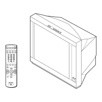
RM-951
TABLE OF CONTENTS
Section Title Page
SELF DIAGNOSIS FUNCTION............................... 4
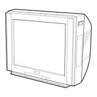
1. GENERAL ....................................................................... 8
2. DISASSEMBLY
2-1. Rear Panel Removal ................................................ 30
2-2. Speaker Box Removal ............................................. 30
2-3. Chassis Assy Removal ............................................ 30
2-4. Service Position....................................................... 30
2-5. D1 and DH Boards Removal .................................. 31
2-6. J1 Board and RF Splitter Removal ......................... 31
2-7. V1 and P Boards Removal ...................................... 32
2-8. A and B Boards Removal ........................................ 32
2-9. H1 Board Removal .................................................. 32
2-10. Demagnetization Coil Removal .............................. 32
2-11. Top Switch Removal ............................................... 33
2-12. Picture Tube Removal ............................................. 33
3. SET-UP ADJUSTMENTS
3-1. Beam Landing Adjustment...................................... 35
3-2. Convergence Adjustment ........................................ 36
3-3. Focus Adjustment .................................................... 38
3-4. Neck Assy Twist Adjustment .................................. 38
3-5. G2 (Screen) and White Blance Adjustment ............ 39
4. CIRCUIT ADJUSTMENTS
4-1. Adjustments with Commander ............................... 40
4-2. Adjustment Method ................................................. 41
4-3. Picture Quality Adjustments ................................... 48
4-4. A Board Adjustment After IC003 (Memory)
Replacement ............................................................ 49
4-5. Picture Distortion Adjustment................................. 50
Section Title Page
5. DIAGRAMS
5-1. Block Diagrams ....................................................... 51
5-2. Frame Schematic Diagram ...................................... 61
5-3 Circuit Boards Location .......................................... 65
5-4. Schematic Diagrams and Printed Wiring Boards ... 65
(1) Schematic Diagram of A Board .............................. 66
(2) Schematic Diagram of B Board .............................. 77
(3) Schematic Diagram of P Board ............................... 85
(4) Schematic Diagrams of D2 and J1 Boards ............ 91
(5) Schematic Diagrams of H1 and F Boards .............. 95
(6) Schematic Diagrams of DH and VM2 Boards ....... 99
(7) Schematic Diagrams of C and B4 Boards .............. 103
(8) Schematic Diagram of V1 Board ............................ 107
5-5. Semiconductors ....................................................... 110
6. EXPLODED VIEWS
6-1. Picture Tube ............................................................. 112
6-2. Chassis ..................................................................... 113
7. ELECTRICAL PARTS LIST...................................... 114
 Loading...