Connecting optional components
You can connect optional audio/video components, such as a VCR, multi disc player,
camcorder, video game, or stereo system. For operations of the connected equipment,
see pages 10 and 25.
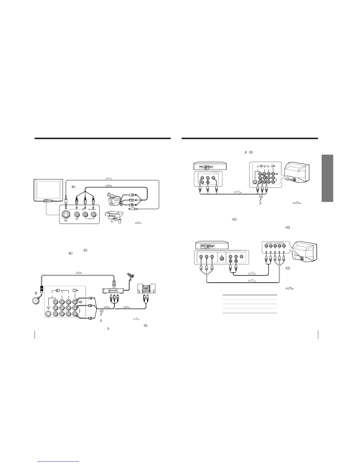
Connecting a camcorder/video game equipment
using the … (video input) jacks
Notes
• You can also connect video equipment to the … 1, 2, or 3 (video input)
jacks at the rear of your TV.
• Do not have concurrent connections of video equipment to the … 3
(video input) jacks at the front and the … 3 (video input) jacks at the rear
of your TV; otherwise, the picture will not be displayed properly on the
screen.
• When both the
(S video input) and … 1 (video input) are connected,
the
␣ (S video input) is automatically selected. To view the video input
to … 1 (video input), disconnect the S video cable.
Connecting audio/video equipment using the Ú
(monitor output) jacks
Note
• When connecting a monaural VCR, connect the yellow plug to
(the
yellow jack) and the black plug to
-L (MONO) (the white jack).
To S video output
Front of TV
Camcorder
Video game
equipment
To video and
audio outputs
: Signal flow
To
(S video
input)
To
…
3
(video input)
or
Audio/Video cable (not supplied)
S video cable (not supplied)
(yellow)
-L (MONO)
(white)
-R (red)
Rear of TV
To
antenna
output
To video and
audio inputs
or
Audio system
To
audio
inputs
VCR
: Signal flow
To Ú
(monitor
output)
Antenna cable (not supplied)
Audio/Video cable
(not supplied)
or
Notes
• Some DVD player terminals may be labeled differently:
• Since the high quality pictures on a DVD disc contain a lot of information,
picture noise may appear. In this case, adjust the sharpness (“SHARP”) in the
PERSONAL ADJUST menu of the PICTURE MODE menu (see page 30).
• Connect your DVD player directly to your TV. Connecting the DVD player
through other video equipment will cause unwanted picture noise.
DVD player
Audio/Video cable
(not supplied)
DVD player
To
L (white)
R (red)
Audio cable
(not supplied)
To component
video output
Component
video cable
(not supplied)
(yellow)
-L (MONO) (white)
-R (red)
To … 1, 2, or 3
(video input)
: Signal flow
To audio
output
: Signal flow
To
(component
video input)
Connect To (on the DVD player)
Y (green) Y
C
B
(blue) C
b
, B-Y or P
B
C
R
(red) C
r
, R-Y or P
R
Connecting a DVD player
Connect … 1, 2, or 3 (video input)
/ (audio/video) connectors on your TV to
LINE OUT on your DVD player.
Connecting a DVD player with component video
output connectors
1 Connect R and L under
(component video input) on your TV to the LINE OUT,
AUDIO R and L output connectors on your DVD player.
2 Using a component video cable, connect Y, C
B, and C
R under (component video
input) on your TV to the COMPONENT VIDEO OUT Y, C
B, and CR output
connectors on your DVD player.



 To Next Page