2-3
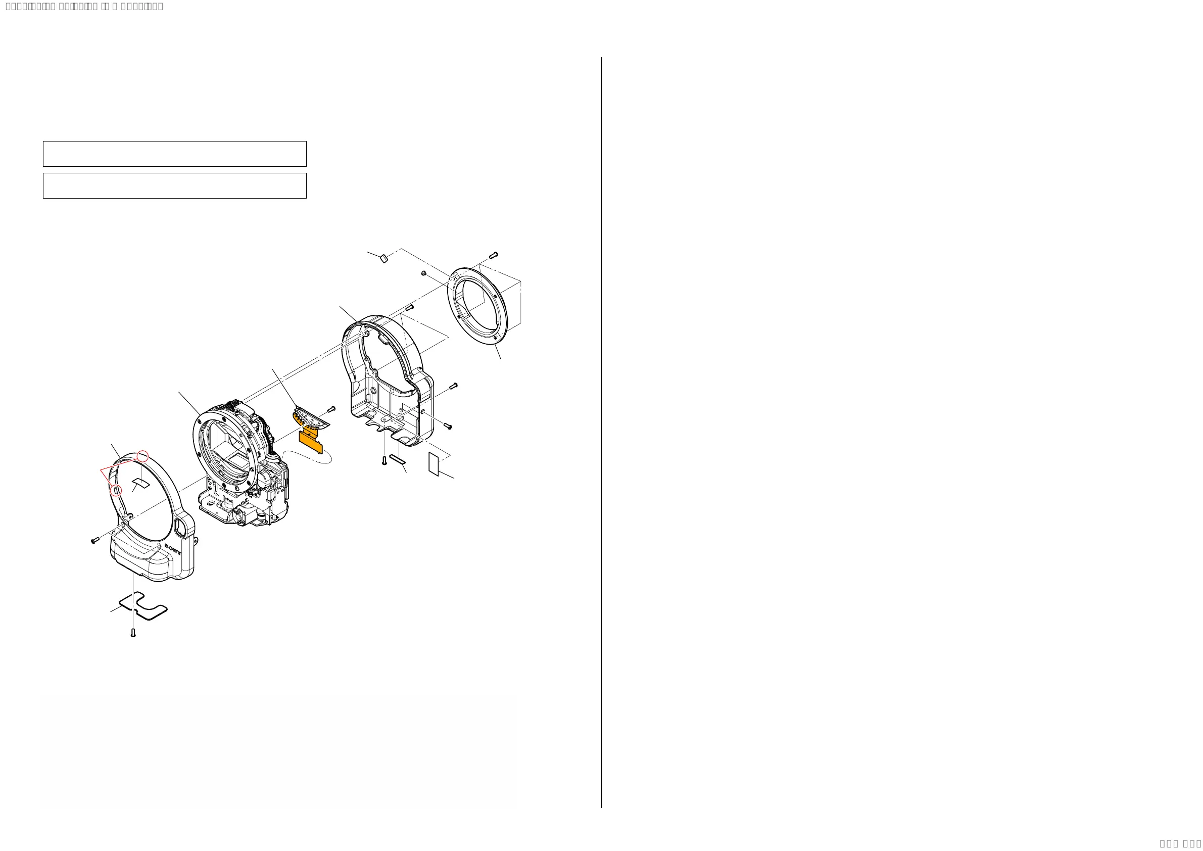
2-1. EXPLODED VIEWS
2-1-1. OVERALL SECTION
ns: not supplied
.
Ref. No. Part No. Description
6
7
9
#89
#113
#155
2-
#193 2-684-244-01 STOPPER SCREW (Note 4)
1. Remove the numerical order (1 to 4) in the left figure.
DISASSEMBLY
1 #89 X 4
(Claws)
#155
#155
#113
#113
#113
#113
#155
#89
1 (Note 2)
2
3
6 (Note 3)
7
9 (Note 1)
ns
3
4
4
1
5
2
Main Section
(See page 2-4)
#193
(Note 4)
2 #155 X 3 → #113 X 3
Back View
#89
#89
#155
#113
#113
#113 #155
Right ViewBack View Bottom View
Note 1: Refer to “Assembly-1: Notes on assembling the MB E
Mount” when assembling.
Note 2: Refer to “Assembly-2: Disassembly/Installation caution of
the CV Front Cover” when assembling.
Note 1:
組立時は“Assembly-1: Notes on assembling the MB E
Mount”を参照してください。
Note 2:
組立時は“Assembly-2: Disassembly/Installation caution of
the CV Front Cover”を参照してください。
Note
If the decoration part and black screws are appearance-degraded by
paint peeling, replace them.
外装部品と黒色のねじは,色剥がれなどで体裁品質が低下した場合,
交換してください。
Note 3: Refer to “Assembly-3: Note on installing the JS Absorption
Sheet” when installing.
Note 3:
貼り付け時は“Assembly-3: Note on installing the JS Absorp-
tion Sheet”を参照してください。
Note 4: When install the screw #193, apply the LOCTITE 460 or the
equivalent.
Note 4:
#193のねじを取り付ける際は,ロックタイト460または相当
品を塗布してください。
Screw
#89: M2.0 X 5.5 (Tapping)
(Silver)
2-695-575-01
5.5
2.0
#113: M1.7 X 5.0
(Black)
2-635-562-41
5.0
1.7
1.7
6.0
#155: M1.7 X 6.0 (Tapping)
(Black)
3-080-204-31
#193: M1.4 X 1.2
(Silver)
2-684-244-01
1.2
1.4
3 #155 X 2 → #113 X 1 4 #155 X 1
#155
Front View
Bottom View
#113
#155
Front View
SYSSET
2021/07/2107:13:38(GMT+09:00)