Do you have a question about the Sony MHC-6800 and is the answer not in the manual?
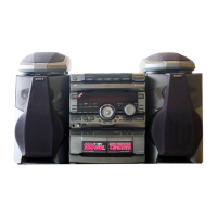
Lists the component models comprising the MHC-6800 system.
Details power, dimensions, mass, and supplied accessories.
Notes on stocked and critical safety components for parts.
Audio and video input/output specifications.
Critical component warnings and French safety advisory.
Procedures for service modes, power control, and test functions.
Instructions for positioning the unit for service access.
Visual layout of circuit boards within the unit.
Overall system block diagram showing interconnections.
Diagrams showing pin configurations for semiconductors.
Component layout on DSP and PIN JACK boards.
Schematics for DSP/PIN JACK and POWER/MICOM/PANEL sections.
Exploded view of the unit's cabinet assembly.
Power output and distortion specs for various models.
Model number labels and power requirements by region.
Identification of front panel controls and indicators.
Procedure for front panel disassembly.
Procedures for disassembling the volume board and back panel.
Procedures for removing heat sink and main board.
Lead configurations for semiconductors.
Visual layout of circuit boards.
Component layout for various boards.
Schematics for main section and power.
Exploded view of the cabinet and its components.
Exploded view of the chassis and frame assemblies.
Speaker system specs: driver types, power, sensitivity, impedance.
Diagram showing speaker connections to the unit.
Procedures for disassembling front panel and mounted board.
Recording system, frequency response, wow/flutter.
Identification of cassette deck controls and indicators.
Procedures for disassembling lid, SW board, retainer, front panel, MD block, TC main board, power board.
Procedures for disassembling mechanism deck and motors.
General precautions for mechanical and electrical adjustments.
Adjustment procedures for CD section and tuner section.
Procedures for playback level, tape speed, bias, and record level adjustments.
Layout of circuit boards within the cassette deck.
Lead configuration diagrams for semiconductors.
Component layout for various boards.
Schematic diagrams for main and connector/power sections.
Exploded views of cabinet, cassette holder, and mechanism deck.
Tuner and CD player specifications.
Model identification for the Tuner CD Player.
Precautions for handling the optical pick-up block due to ESD.
Procedures for checking laser diode emission and focus search.
Power supply for servicing and forceful power ON procedure.
Procedures for voltage measurements and FL tube check.
Identification of Tuner/CD Player controls and indicators.
Identification of tuner controls and buttons.
Identification of CD player controls and buttons.
Description of display window functions.
Steps for automatic radio station tuning.
Steps for manual radio station tuning.
Explains the TUNED and STEREO indicators on the display.
Guidance for adjusting the AM loop antenna for optimal reception.
Advice on improving FM reception by using MONO mode.
Procedure to change the MW tuning interval setting.
Procedures for S Curve, RF Level, and E-F Balance checks.
Procedures for RF PLL, FM, AM, and SW tuning adjustments.
Procedures for playback level, tape speed, bias, and record level adjustments.
Location of circuit boards in the HCD-H6800.
Block diagrams for key ICs.
Pin assignments and functions for IC104 and IC205.
Exploded views of cabinet, cassette holder, and mechanism deck.
| Brand | Sony |
|---|---|
| Model | MHC-6800 |
| Category | Stereo System |
| Language | English |