pg. 19
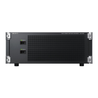
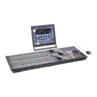
The following shows the backplane of the MVS-7000X’s DME I/O:
BNC
BNC SIGNAL(DME2) BNC
BNC SIGNAL(DME2)
1 CH1 V Out 9 CH5 V Out 1 CH1 V In 9 CH5 V In
2 CH1 K Out 10 CH5 K Out 2 CH1 K In 10 CH5 K In
3 CH2 V Out 11 CH6 V Out 3 CH2 V In 11 CH6 V In
4 CH2 K Out 12 CH6 K Out 4 CH2 K In 12 CH6 K In
5 CH3 V Out 13 CH7 V Out 5 CH3 V In 13 CH7 V In
6 CH3 K Out 14 CH7 K Out 6 CH3 K In 14 CH7 K In
7 CH4 V Out 15 CH8 V Out 7 CH4 V In 15 CH8 V In
8 CH4 K Out 16 CH8 K Out 8 CH4 K In 16 CH8 K In
Notes:
1. If an internal DME is installed it will always be DME1 (Unit ID 1) and BNC connectors 1-8 for both
input and output are not used.
2. If a chassis of MVE-8000A or MVE-9000 is installed in addition to the internal DME, connect the
external chassis to BNC connectors 9-16 (CH5-8).
3. If no internal DME is installed then BNC Connectors 1-8 (CH1-4) are for the first external chassis and
9-16 (CH5-8) are for the second external chassis.

 Loading...


