pg. 29
MENU DISPLAY (15-pin) is a mirror of the touchscreen menu display. This is useful during training to
display the menu on a larger screen or projector for all to see. It can also be used in an emergency if a
fault develops in the touchscreen. MENU DISPLAY is a standard analog VGA connector.
EXT DISPLAY (15-pin) is used, exclusively, when the Plug-In Editor option is installed. This will be the EDL
display. EXT DISPLAY is a standard analog VGA connector.
REMOTE is to connect Aux Bus remote panels (1 or 3 RU – MKS-8080 or MKS-8082, respectively) to the
switcher. If you have one or more of these panels, please refer to the installation instructions that came
with them.
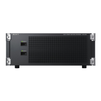
DME Chassis
If you have an MVE-8000A or MVE-9000A DME chassis in your switcher they need to be wired for video
into and out of the main switcher chassis. Please see the section above (under switcher wiring) on how
to wire-in the DME channels. Note that there are wiring instructions specific to the model switcher you
purchased.
Each DME chassis also require house “black” reference. If you are not looping reference, please
terminate with a 75-ohm terminating resistor.
Any external DME chassis must also be rack-mounted with proper support as they are heavy. In almost
all cases, there will be a backup power supply to plug-in along with the primary.
If you have a 7000X switcher then there is a good chance you will not have any external DME chassis as
the 7000X supports up to 4 channels of plug-in DME. However, the 7000X can also accommodate an
additional 4 channels of external DME to augment the internal 4. In very rare cases, a 7000X can have 8
channels (2 chassis) of external DME without using any internal DMEs.
If you have an 8000X switcher, then all DME channels will be external.
Device Control Unit (DCU)
You will likely have either a MKS-2700 or MKS-8700 Device Control Unit (DCU) that must be rack-
mounted as well. The MKS-2700 is a small, 1RU frame that has 32 parallel Tally/GPI outputs and 6 RS-
422 connectors. The MKS-8700 is a larger, 3RU frame that has 5 slots for option cards. Currently there
are two option cards offered: the MKS-8701 is a 54 Tally/GPI Output card and the MKS-8702 is a 6 RS-
422 card. If you ordered a MKS-8700 DCU, it is likely all the option cards have already been installed. If
they came separately, please see the install manual for the MKS-8700 for instructions for installing
boards.
The DCU chassis also require house “black” reference. If you are not looping reference, please
terminate with a 75-ohm terminating resistor.
The DCU must also be rack-mounted with proper support. In almost all cases, there will be a backup
power supply to plug-in along with the primary.

 Loading...


