pg. 27
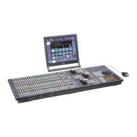
If you have a 2, or even a 1, M/E panel, then the Aux portion is always “integrated” into the panel.
2 M/E Panel with Integrated Aux
Connecting the Panel
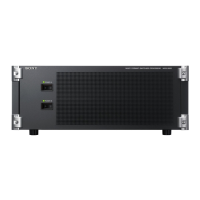
First make sure the SCU (MKS-8010B) is powered down. Connecting control panel cables or even
adding and removing individual panel modules while power is applied can result in blown fuses which
are time consuming to replace.
Next, locate the SWC cables (thick, black cables with 50 pin D-Sub connectors). One cable is going to
connect the main panel (the big part) to the SCU. On the main panel, the connector will be in the back
on the right side (if you are looking from the back). On the SCU, connect this cable to “MAIN PANEL”.
If you have a separate Aux row, please connect another SWC cable to the back of the aux row and the
other end to the SCU on the port marked “EXT PANEL1”. If your Aux is integrated into the main panel
(no separate aux row) then there is nothing to connect. The switcher processor will determine which
row is the aux automatically.
If you are using an MVS-8000X switcher and have a 5 M/E panel, you will have another separate row for
M/E 4. This will connect with an SWC cable in the same manner as the Aux row, except connect M/E 4
to the EXT PANEL2.
Connect another SWC cable to the menu display (it’s in the back). The other end goes to the SCU port
marked “MENU”.
External Adapters
Depending on your configuration, you may also have external modules. Sometimes this is because the
standard layout of the control panel isn’t large enough to accommodate all the requested modules,
other times it’s because the operator wanted a module mounted outside the panel. Since the modules
are all designed to fit within the main panel, using a module outside of the panel requires an adapter.
For all modules, except the USB/Memory Stick Module, this adapter is the MKS-8075A. Please refer to

 Loading...


