EasyManua.ls Logo

Sony MZ-N520 User Manual

Sony MZ-N520
68 pages
To Next Page IconTo Next Page
Page #1 background imageLoading...
Page #1 background image
SERVICE MANUAL
PORTABLE MINIDISC RECORDER
AEP Model
UK Model
MZ-N520
E Model
MZ-N520/N520CK
Australian Model
MZ-N520
SPECIFICATIONS
MZ-N520/N520CK
US and foreign patents licensed from Dolby
Laboratories.
– Continued on next page –
Model Name Using Similar Mechanism MZ-N510
Mechanism Type MT-MZN710-177
Optical Pick-up Name LCX-5R
Ver 1.0 2004.04
9-877-751-01 Sony Corporation
2004D1678-1 Personal Audio Company
© 2004.04 Published by Sony Engineering Corporation
Audio playing system
MiniDisc digital audio system
Laser diode properties
Material: GaAlAs
Wavelength: λ = 790 nm
Emission duration: continuous
Laser output: less than 44.6 µW
(This output is the value measured at a distance
of 200 mm from the lens surface on the optical
pick-up block with 7 mm aperture.)
Recording and playback time (when
using MDW-80)
Maximum 160 min. in monaural
Maximum 320 min. in LP4 stereo
Revolutions
380 rpm to 2,700 rpm (CLV)
Error correction
ACIRC (Advanced Cross Interleave Reed
Solomon Code)
Sampling frequency
44.1 kHz
Sampling rate converter
Input: 32 kHz/44.1 kHz/48 kHz
Coding
AT RAC (Adaptive TRansform Acoustic
Coding)
AT RAC 3 — LP2/LP4
photo : silver model
SonicStage, MD Simple Burner,
OpenMG, Magic Gate, MagicGate
Memory Stick, Memory Stick, Net MD,
AT RAC, ATRAC3, ATRAC3plus and
their logos are trademarks of Sony
Corporation.
Microsoft, Windows, Windows NT and
Windows Media are trademarks or
registered trademarks of Microsoft
Corporation in the United States and /or
other countries.
IBM and PC/AT are registered
trademarks of International Business
Machines Corporation.
Macintosh is a trademark of Apple
Computer, Inc. in the United States and/
or other countries.
MMX and Pentium are trademarks or
registered trademarks of Intel
Corporation.
All other trademarks and registered
trademarks are trademarks or registered
trademarks of their respective holders.
™ and ® marks are omitted in this
manual.
CD and music-related data from
Gracenote, Inc., copyright © 2000-2003
Gracenote. Gracenote CDDB
R
Client
Software, copyright 2000-2003
Gracenote. This product and service
may practice one or more of the
following U.S. Patents: #5,987,525;
#6,061,680; #6,154,773, #6,161,132,
#6,230,192, #6,230,207, #6,240,459,
#6,330,593 and other patents issued or
pending.
Gracenote and CDDB are registered
trademarks of Gracenote. The
Gracenote logo and logotype, the
Gracenote CDDB logo, and the
“Powered by Gracenote” logo are
trademarks of Gracenote.
Question and Answer IconNeed help?

Do you have a question about the Sony MZ-N520 and is the answer not in the manual?

Sony MZ-N520 Specifications

General IconGeneral
BrandSony
ModelMZ-N520
CategoryCD Player
LanguageEnglish

Summary

SECTION 1 SERVICING NOTES

Optical Pick-up and Laser Diode Handling

Precautions for handling optical pick-up components and laser diode, including ESD protection.

System Requirements for Software

Details the necessary computer hardware and OS for using bundled software like SonicStage.

SECTION 2 GENERAL

Recorder and Display Overview

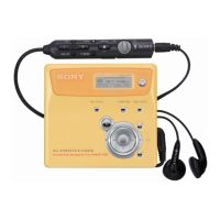
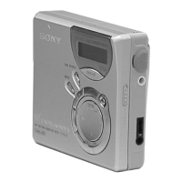
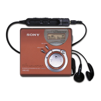
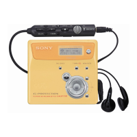
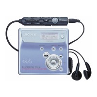
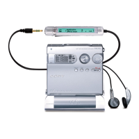
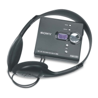
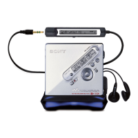
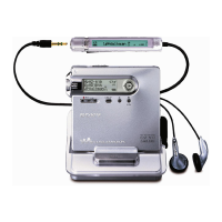
Provides a general description of the recorder's layout, controls, and display window.

Remote Control Operation

Explains the functions of the headphones with an integrated remote control.

SECTION 3 DISASSEMBLY

Case and Panel Disassembly

Step-by-step guide for removing the outer case and upper panel sections.

Main Board and Mechanism Deck Removal

Procedures for detaching the main board and the mechanism deck assembly.

Component Disassembly (Motors, OP Assy)

Instructions for removing specific internal components like motors and the optical pick-up service assembly.

SECTION 4 TEST MODE

Test Mode Entry and Operation

Methods for entering, navigating, and releasing the device's test mode.

Manual Mode Adjustments

Procedures for performing specific adjustments using the manual mode within the test function.

Self-Diagnosis and Error Display

How to access and interpret self-diagnosis results and error codes for fault analysis.

Sound Skip and Key Check Procedures

Steps for performing sound skip error checks and verifying button functionality in test modes.

SECTION 5 ELECTRICAL ADJUSTMENTS

Adjustment Precautions and Preparation

Critical safety notes, tools, and preliminary steps required before starting electrical adjustments.

NV Reset, Temperature, and Power Supply Adjustments

Procedures for resetting NV values, correcting temperature, and adjusting power supply parameters.

Laser Power Check and Overall Adjustment

Steps for measuring laser power and performing CD/MO overall adjustments.

Patch Data and NV Value Rewriting

Detailed instructions for rewriting patch data and NV values, essential after main board replacement.

SECTION 6 DIAGRAMS

Printed Wiring Board Layouts

Visual guides showing the component placement on the main board's printed wiring.

Main Board Schematic Diagrams

Electrical schematics for the main board, illustrating circuit connections and components.

IC Block Diagrams and Pin Functions

Block diagrams of integrated circuits and detailed descriptions of each pin's function.

SECTION 7 EXPLODED VIEWS

Case and Chassis Exploded Views

Diagrams showing the breakdown of the unit's outer case and chassis assembly.

Mechanism Deck Exploded Views

Detailed exploded views of the internal mechanism deck sections for parts identification.

SECTION 8 ELECTRICAL PARTS LIST

Component Lists (Capacitors, Resistors, Semiconductors)

Lists of capacitors, resistors, and semiconductors with part numbers and specifications.

Connectors, Switches, and Miscellaneous Parts

Lists of connectors, switches, fuses, and other miscellaneous parts with their part numbers.

REVISION HISTORY

Related product manuals