26
MZ-N520/N520CK
Laser Power Check
Note: If result of measurement of the laser power does not satisfy
the specification, either replace the OP (optical pick-up unit)
or check whether the laser circuit block is working correctly.
When the result of laser power measurement does not satisfy
the specification even though the laser circuit block is con-
firmed to be working correctly, replace the OP (optical pick-
up unit).
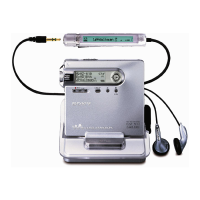
• Connection
• Checking method
1. Select the manual mode of test mode (see page 14), and set the
laser power check mode (item number 010).
2. Press the . key continuously until the optical pick-up
moves to the most inward track.
3. Open the cover and set the laser power meter on the objective
lens of the optical pick-up.
4. Press the > key, and set the laser MO read check mode
(item number 011).
5. Check that the laser power meter reading is 0.800 ± 0.10
mW.
6. Press the > key, and set the laser CD read check mode (item
number 012).
7. Check that the laser power meter reading is 0.910 ± 0.11 mW.
8. Press the > key, and set the laser MO (X2 speed) write
check mode (item number 013).
9. Check that the laser power meter reading is 4.95 ± 0.59 mW.
10. Press the
> key, and set the laser MO (X4 speed) write
check mode (item number 014).
11. Check that the laser power meter reading is 5.93 ± 0.71mW.
12. Press the xCANCEL/CHG key to quit the manual mode, and
activate the test mode (display check mode).
Adjustment required before Overall Adjustment
Note1 :Modify four adjusted values through the following proce-
dure before performing the CD overall adjustment and MO
overall adjustment.
Note2 :In the case of the microcomputer version 1.200 or more,
this adjustment is unnecessary.
• Adjusted values modifying procedure
1. Select manual mode of the test mode, and set item number
860 (see page 14).
2. Press the > key to set item number 861.
3. Adjust with the [VOL +] key (adjusted value up) or [VOL --]
key (adjusted value down) so that the adjusted value becomes
3E.
4. Press the X key or press the key on the remote com-
mander to write the adjusted value.
5. Press the > key to set item number 862.
6. Adjust with the [VOL +] key (adjusted value up) or [VOL --]
key (adjusted value down) so that the adjusted value becomes
00.
7. Press the X key or press the key on the remote com-
mander to write the adjusted value.
8. Press the > key to set item number 863.
9. Adjust with the [VOL +] key (adjusted value up) or [VOL --]
key (adjusted value down) so that the adjusted value becomes
37.
10. Press the X key or press the key on the remote com-
mander to write the adjusted value.
11. Press the > key to set item number 864 .
0 10 Laser
Set LCD display
Set LCD display
###S**
0 11
address adjusted valu
 Loading...