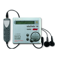
Do you have a question about the Sony MZ-R55 and is the answer not in the manual?
Detailed technical specifications of the portable MiniDisc recorder, including frequency response, inputs, and outputs.
Methods for entering the test mode for self-diagnosis and adjustments.
How the LCD displays change when the device is in test mode.
Steps to enter and navigate the self-diagnostic mode to view error history.
Procedures for resetting error codes and total recording time after repairs.
Procedure for removing the main board from the chassis.
Overview of the overall and servo modes for automatic adjustments.
Instructions on how to enter the test mode.
Detailed guide on performing manual adjustments within different modes (Servo, Audio, Mechanism, Power).
Detailed steps for adjusting audio parameters within the audio mode.
Procedure for performing overall automatic adjustments for CD and MO disks.
Details on the automatic adjustment process for CD playback and read functions.
Table listing MO automatic adjustment modes and their descriptions.
General precautions and guidelines before performing electrical adjustments.
Procedure for measuring and adjusting laser power output for CD and MO modes.
Steps for adjusting the MO traverse mechanism for optimal performance.
Steps to adjust the 2.65V power supply using RV901.
Pin descriptions for IC503 CXD2652AR (Digital Servo, ATRAC).
Pin descriptions for IC503 CXD2652AR (Digital Servo, ATRAC).
Pin descriptions for IC802 CXP740010 (System Control).
Exploded view of the panel section, showing component parts and their references.
Exploded view of the mechanism deck section, detailing its components.
Safety precautions when checking the laser diode emission.
Handling precautions for the optical pick-up to prevent static damage.
| Recording Modes | SP, LP2, LP4 |
|---|---|
| Sampling Frequency | 44.1 kHz |
| Headphone Output | Yes |
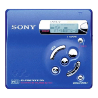
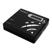
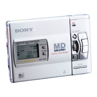
| Type | MiniDisc Player |
| Frequency Response | 20 Hz - 20 kHz (±3 dB) |
| Battery Type | 2 x AA |
| Digital Input | Optical |