EasyManua.ls Logo

Sony MZ-R700 Service Manual

Sony MZ-R700
56 pages
To Next Page IconTo Next Page
Page #1 background imageLoading...
Page #1 background image
1
MZ-G750/R700
SERVICE MANUAL
FM/AM PORTABLE MINIDISC RECORDER
Model Name Using Similar Mechanism NEW
Mechanism Type MT-MZR700-172
Optical Pick-up Name LCX-4R
(Photo: MZ-G750)
MD recorder
Audio playing system
MiniDisc digital audio system
Laser diode properties
Material: GaAlAs MQW
Wavelength: λ = 790 nm
Emission duration: continuous
Laser output: less than 44.6 µW
(This output is the value measured at a
distance of 200 mm from the lens surface
on the optical pick-up block with 7 mm
aperture.)
Recording and playback time
When using MDW-80
Maximum 160 min. in monaural
Maximum 320 min. in stereo
Revolutions
350 rpm to 2,800 rpm (CLV)
Error correction
ACIRC (Advanced Cross Interleave Reed
Solomon Code)
Sampling frequency
44.1 kHz
Sampling rate converter
Input: 32 kHz/44.1 kHz/48 kHz
Coding
ATRAC (Adaptive TRansform Acoustic
Coding)
ATRAC3-LP2
ATRAC3-LP4
SPECIFICATIONS
Modulation system
EFM (Eight to Fourteen Modulation)
Number of channels
2 stereo channels
1 monaural channel
Frequency response
20 to 20,000 Hz ± 3 dB
Wow and Flutter
Below measurable limit
Inputs
Microphone: stereo mini-jack, minimum
input level 0.25 mV
Line in: stereo mini-jack, minimum input
level 49 mV
Optical (Digital) in: optical (digital) mini-
jack
Outputs
i: stereo mini-jack, maximum output level
5 mW + 5 mW, load impedance 16 ohm
Radio (MZ-G750)
Frequency range
AM: 530-1,710 kHz (US,Canada, and
Central and South America models)
531-1,602 kHz (Other models)
FM: 87.5-108.0 MHz
General
Power requirements
Sony AC Power Adaptor (supplied)
connected at the DC IN 3 V jack:
120 V AC, 60 Hz (U.S.A.,Canadian and
Taiwan model)
230 V AC, 50/60 Hz (AEP model)
240 V AC, 50 Hz (Australian model)
220 V AC, 50 Hz (Chinese model)
230-240 V AC, 50 Hz (UK and Hong
Kong model)
220 V AC, 50 Hz (Argentina model)
110/220 V AC, 60 Hz (Korean model)
100-240 V AC, 50/60 Hz (Other models)
Nickel cadmium rechargeable battery
NC-WMAA (supplied)
LR6 (size AA) alkaline battery (not
supplied)
– Continued on next page –
US Model
Canadian Model
AEP Model
UK Model
E Model
Australian Model
Tourist Model
Chinese Model
US and foreign patents licensed from Dolby
Laboratories Licensing Corporation.
Ver 1.0 2001. 01
MZ-G750
PORTABLE MINIDISC RECORDER
MZ-R700
Ver 1.1 2001. 02
Sony Corporation
Audio Entertainment Group
General Engineering Dept.
9-873-045-12
2001B0400-1
© 2001. 2

Other manuals for Sony MZ-R700

Question and Answer IconNeed help?

Do you have a question about the Sony MZ-R700 and is the answer not in the manual?

Sony MZ-R700 Specifications

General IconGeneral
BrandSony
ModelMZ-R700
CategoryCD Player
LanguageEnglish

Summary

Servicing Notes and Handling Precautions

Handling Precautions for Optical Pick-up and Laser Diode

Safety and handling guidelines for optical pick-up blocks and laser diodes during servicing.

General Information and Controls

MZ-G750 Controls and Display Overview

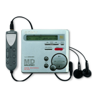
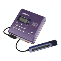
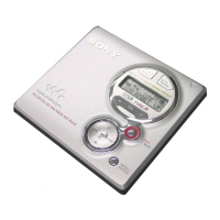
Overview of the MZ-G750 recorder and remote control buttons and displays.

MZ-R700 Controls and Display Overview

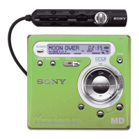
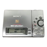
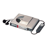
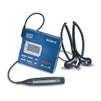
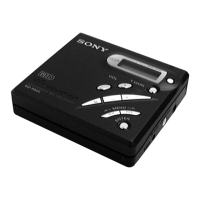
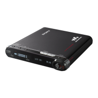
Overview of the MZ-R700 recorder and remote control buttons and displays.

Disassembly Procedures

Panel Assemblies Disassembly

Steps for disassembling the lower and upper panel assemblies.

Module and Main Board Removal

Procedures for removing the LCD module and main board.

MD Mechanism Deck and Service Assembly Disassembly

Disassembly of the MD mechanism deck and service assembly.

Holder, Motor Flexible Board, and DC Motors Disassembly

Steps to disassemble holder, motor flexible board, and DC motors.

Specific DC Motor Component Disassembly

Detailed disassembly procedures for DC motors (M601, M602, M603).

Test Mode Operations

Test Mode Overview and Setting

Explains the test mode, setting, operation, and releasing procedures.

Test Mode Configuration and Manual Mode

Details on configuring test modes and using the manual mode for adjustments.

Diagnostic and Error Handling Modes

Covers self-diagnosis result display and error indication codes.

Error Reset and Sound Skip Check

Procedures for resetting error codes and checking sound skip results.

Key Check Mode Functionality

Procedure for checking the functionality of the set and remote commander keys.

Electrical Adjustments

Adjustment Overview, Precautions, and Sequence

General information, precautions, and the sequence for electrical adjustments.

NV Reset and Power Supply Adjustment

Steps for NV reset and manual power supply voltage adjustments.

Temperature, Laser, and Overall Adjustments

Procedures for temperature correction, laser power check, and overall adjustment modes.

Resume Clear and Patch Data Rewriting

Instructions for resume clear and patch data rewriting after adjustments.

Diagrams and Circuit Information

IC Pin Function Descriptions

Detailed pin assignments and functions for ICs used in the system.

System Block Diagrams

High-level block diagrams showing servo, audio, and power sections.

Printed Wiring and Schematic Diagrams

Detailed board layouts and circuit schematics for the main board.

IC Block Diagrams

Visual representations of internal IC functionalities and connections.

Exploded Views and Parts Identification

Panel Section Exploded View

Exploded view and parts list for the unit's panel sections.

Chassis Section Exploded View

Exploded view and parts list for the unit's chassis and main board components.

MD Mechanism Deck Exploded View

Exploded view and parts list for the MD mechanism deck assembly.

Electrical Parts List

Capacitors and Resistors

Comprehensive list of capacitor and resistor part numbers, values, and tolerances.

Semiconductors and Connectors

Lists ICs, diodes, transistors, connectors, and other component types.

Miscellaneous Parts and Accessories

Lists miscellaneous parts, manuals, and packing materials.

Related product manuals