Do you have a question about the Sony MZ-R37 and is the answer not in the manual?
Detailed technical specifications covering audio response, inputs, outputs, and general features.
Warnings regarding laser safety and handling of the optical pick-up to prevent damage.
Guidelines for handling flexible circuit boards and chip components during repair.
Highlights critical components identified by marks that require specific safety replacement procedures.
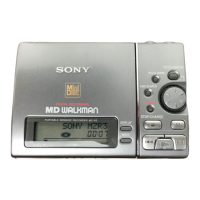
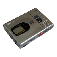
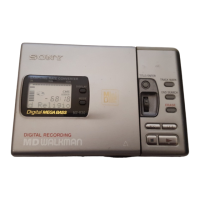
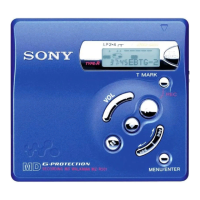
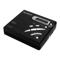
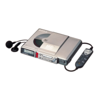
Detailed explanation of the recorder's buttons, switches, and indicators.
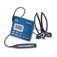
Description of the headphones and remote control features and operation.
Explains how to enter, operate, and exit the device's test mode for diagnostics.
Describes how to initiate and interpret the self-diagnostic results and error codes.
Procedure for clearing error codes and total recording time data after repairs.
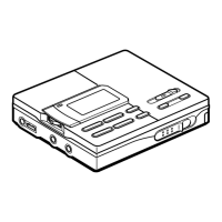
Step-by-step guide for removing the bottom and front panels of the unit.
Instructions for disassembling and removing the LCD module and connectors.
Steps for removing the main circuit board and the main cabinet assembly.
Procedures for disassembling the optical pick-up block and holder assemblies.
General explanation of the test mode, its structure, and capabilities for adjustment.
Detailed procedures for performing servo, audio, mechanism, and power adjustments in manual mode.
Instructions for the automatic overall adjustment mode for CD and MO disks.
Important safety and procedural notes, and required tools for electrical adjustments.
Step-by-step guides for adjusting the MO disk traverse mechanism and laser power.
Procedures for adjusting CD traverse mechanism and RF signal level for optimal playback.
Detailed pin assignments and functions for various integrated circuits used in the device.
Visual representations of the servo, audio, and system control circuitry's functional blocks.
Diagram showing component placement on the main printed circuit board.
Detailed schematic diagrams illustrating the electronic circuit connections across three parts.
Exploded view of the unit's panel section with part number references.
Exploded views of the cabinet and mechanism deck, detailing components and assembly.
Comprehensive list of electrical components for the main board with part numbers.
Lists of connectors, diodes, transistors, and resistors with their part numbers.
List of switches, filters, and vibrator components with their respective part numbers.
Specific corrections to exploded views and electrical parts list, detailing part number discrepancies.
| Type | MiniDisc Recorder |
|---|---|
| Sampling Frequency | 44.1 kHz |
| Category | Portable |
| Recording Mode | SP |
| Frequency Response | 20Hz - 20kHz |
| Digital Input | Optical |
| Formats | MiniDisc |
| Output | Headphones |
| Power Supply | 3V DC (battery) or AC adapter |